Ladder Logic
A look at controllers that use ladder logic.
The PLC
Microcontrollers are everywhere today. They are cheap, relatively fast, and easy to use! Using a current IDE makes programming a breeze; couple that with a decent debugger and programming gets even easier. Most of us, including me, take for granted that we can scroll through hundreds of code lines in a few seconds. Need to locate a variable? Ctrl+F and you'll have all of its locations instantly. That’s a luxury that didn't always exist. I’d like to take a look at an industrial control device, the Programmable Logic Controller (PLC).
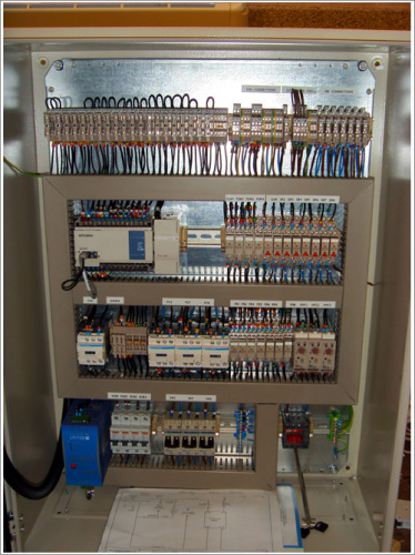
Now hold on. Before you get your caps lock ready, yes I know PLCs are still used in everything everywhere and can be quite modern. I'm talking about really old PLCs. The ones that didn't interface to a computer and had to be programmed directly from a keypad. The Programmable Logic Controller is a term trademarked by Allen-Bradley (Rockwell Automation). PLCs are often used in industrial settings where extreme variations in temperature, vibrations, electrical noise, and mechanical shock are the norm. Before the PLC, relay logic (along with other non-computerized methods) was used to control machinery. Because a 'program' could number in the thousands of relays, changing a single 'line' of code could be extremely time consuming. In a large installment, timing was also an issue. There is a slight delay while the mechanical portion of the relay moves. Times that by hundreds of relays and you may have issues. This created the demand for a simple, input-output operating system that could be easy to implement and easy to program. So was born the PLC.
My PLC
Aside from a few variations, PLCs are programmed primarily with what is called ladder logic ("It's a ladder!"). It is called ladder logic because it looks like a ladder! Ladder logic executes in a very predictable order, top to bottom, with no function calls or other fancy trickery. Modern PLCs can be programmed using an ethernet or RS cable, but older models had to be programmed from a keypad.
Alright, enough history. What I really want to do is show you my PLC. Let's get started.
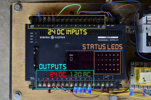
I'm going to be showing you my Series One Junior Programmable Logic Controller. This device resided on a shelf in my father's shop until I was old enough to understand how to use it. I can remember looking at an 8 pin socket relay and thinking it looked like the power crystal for a spaceship. I'm not big on leisurely reading, but I could read 200 page instruction manuals all day. So that is what I did. I picked up the manual and read it front to back in order to get a general understanding of how to use this thing. Let's go over some basics.
The top row is used for 24 VDC inputs. Lots of industrial equipment uses 24 VDC. The bottom terminals are the outputs, the C_ stands for common. So for example, I have 24 VDC connected to terminal C2. When terminal 20,21,22, or 23 is switched ON, it is supplied with 24 VDC. Similarly, C3 supplies terminals 24-27 with 120 VAC. The status LEDs show which inputs are receiving power and which outputs are switched ON. The H and N in the bottom right are the main power to the controller. Finally, the 26 pin connector on the left is where the keypad plugs in.
How about some specifications?
Max of 700 16-bit words, stored in CMOS RAM (needs a battery to retain code)
24 I/O - expandable to 96
2 kHz clock for timing purposes, able to manage 20 simultaneous timers
160 internal coils - think of these as boolean variables with no physical output
155 slots for shift register operations.
The Keypad
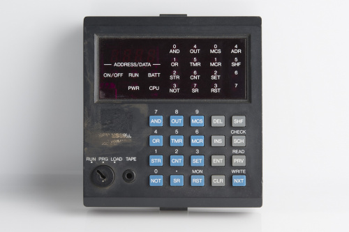
The keypad is used to program the controller. It allows the user to monitor a specific set of inputs/outputs and shows the current memory location 0-699.
Let's go over the key functions. I'll be comparing ladder logic to C style programming.
AND - Equal to && - places contacts in series. Works with inputs and outputs.
OR - Equal to || - places contacts in parallel. Works with inputs and outputs.
STR - Starts a new line of logic. Tells the controller that we are about to enter data.
NOT - Equal to ! - inverts the logic. Works with inputs and outputs.
OUT - The action to be performed upon a logic block being true - normally energizes an external contact or internal coil.
TMR - Creates a new timer function to be used.
CNT - Specifies a counter function to end two logic rungs.
SR - Specifies a shift register function to end 3 logic rungs.
MCS/MCR - Master Control Set/Reset - groups many logic lines into one unit which is governed by a single coil, input, or output. Think emergency stop.
SET - Energizes an internal coil, often used for timing.
RST - De-energizes specified SET coils.
DEL/INS - Delete and insert. Used for deleting a line of code or adding one in, pushing everything down one slot in memory.
ENT - Enters the logic into memory.
CLR - Clears user input.
SHF - Shift - allows access to secondary keys labeled in white above the actual key.
SCH - Search - allows user to search for a logic statement such as an input, output, or coil number.
PRV/NXT - Allow monitoring of I/O states, also scrolls through lines of code.
MON - Allows monitoring of ranges of I/O in groups of 8. Statuses are displayed with an LED.
WRITE - Copies the stored logic through the audio port...to a cassette tape! I think that is awesome.
READ - Load code in from a cassette tape.
CHECK - Checks the RAM vs tape for consistency.
RUN - Puts the PLC into normal operation mode. No code changes allowed.
PRG - Program mode. Allows code input and modification.
LOAD - Prepares to read or write code through the audio port.
TAPE - 3.5mm audio jack.
Code Examples
Let's see some ladder logic!
Pseudocode: If input 4 or output 20 is energized but not input 5, energize output 20.
if( ( 4 || 20 ) && !5 )
    turn 20 on;
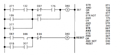
Pseudocode: If (271 and 132), or (135), or (377) are energized and not (37 and 175) or 267, then SET 340 to ON. If (67 and 306) or (15 and 307) are energized but not (36), then RESET coil 340.
if( ( (271 && 132 ) || 135 || 377 ) && ( (!37 && 175 ) || 267 )
    SET 340 ON;

if( ( ( 67 && 306 ) || ( 15 && 307 ) ) && !36 )
    RESET coil 340;
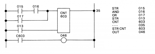
Pseudocode: If (15 and 16) or 17 are toggled, add 1 to 603. If counter 603 reaches 35 counts or more, turn on 46. If 13 is energized then reset timer 603.
POWER = false if 15, 16, and 17 are false. The power to the counter must be toggled in order to increment again.
if( 17 )
    counter 603 = 0;

if( (15 && 16) || 17 && !POWER ) {
    add 1 to 603;
    POWER = true;
}

if( 603 >= 35 )
    turn on 46;

 if( !15 && !16 && !17 )
    POWER = false;
CHALLENGE
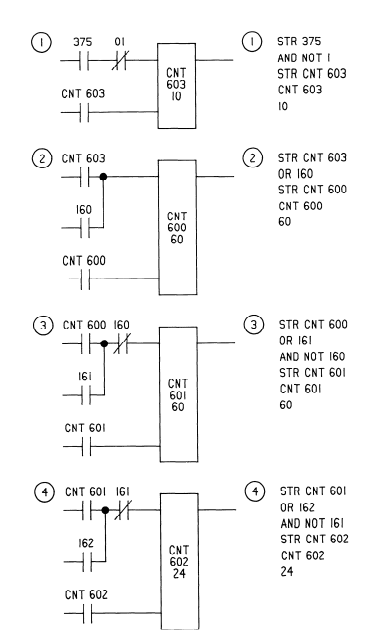
Can you determine what this logic does? Go on, I dare you! Now is your chance to shine. Remember: Numbers 0-16 are inputs, numbers 17-96ish are outputs, numbers 160 through 400ish are internal coils - boolean variables that have no physical output, and numbers 600-620ish are timer coils, they keep time. Annnnnnnnnnnnnddddd GO!
Almost done, I promise
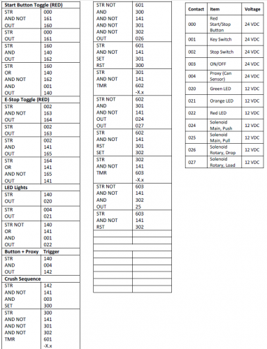
Alright so I have this PLC, a bunch of industrial components, what now? Learning how to use the PLC was one challenge, but the real test was actually doing something with it. I already had most of the parts I needed just sitting around, so I built an aluminum can crusher. Because this post is already running into next week, I'm posting the video, the code, and I'm outta here! Post any questions in the comments below. Oh and thanks for reading this far. Unless you skipped to the end, then boo.
Also, this was filmed 4 years ago. I don't like hearing my own voice so I haven't watched it in 2 years. Don't make fun of me, I am a sensy.
ReplaceMeOpen
ReplaceMeClose
