Why You Should De-Rate Capacitors
Why the voltage rating on capacitors matters and why you should derate them.
ReplaceMeOpen
ReplaceMeClose
Capacitors Galore
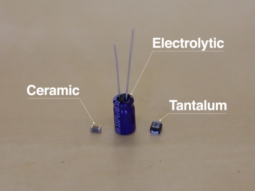
Capacitors are one of the most common elements found in electronics, and they come in a variety of shapes, sizes, and values. There are also many different methods to manufacture a capacitor. As a result, capacitors have a wide array of properties that make some capacitor types better for specific situations. I would like to take three of the most common capacitors - ceramic, electrolytic, and tantalum - and examine their abilities to handle reverse and over-voltage situations. Note: several capacitors were harmed in the making of this post.
Ceramic Capacitors
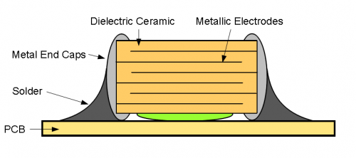
The most common capacitor is the multi-layer ceramic capacitor (MLCC). These are found on almost every piece of electronics, often in small, surface-mount variants. Ceramic capacitors are produced from alternating layers of metal paste and ceramic powder. These devices are then baked at temperatures in excess of 1200°C in a process called sintering, which fuses the ceramic powder into a solid. Both ends of the capacitors are dipped in metal to connect the alternating plates and provide a solderable surface.
Ceramic capacitors are great for a wide range of uses, including coupling, decoupling, filtering, timing, etc. Since they are non-polarized devices, they can be used in AC circuits. Most ceramic capacitors have a fairly high voltage rating. If the capacitor experiences a voltage between its terminals higher than its rated voltage, the dielectric may break down and electrons will flow between the thin metal layers inside of the capacitor, creating a short. Luckily, most ceramic capacitors are built with a hefty safety margin and do not experience any sort of catastrophic failure (such as exploding). However, the rule of thumb dictates that you should derate ceramic capacitors by 50%, which means that if you are expecting to have a maximum of 5V between the capacitor's leads, then you should use a capacitor rated for 10V or more.
One thing to keep in mind is that ceramic capacitors will lose their capacitance value as the voltage approaches and surpasses the rated voltage. You might see a 10uF capacitor rated for 6.3V become 2uF when 6V is applied to the terminals!
Aluminum Electrolytic Capacitors
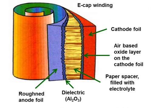
Electrolytic capacitors are also very common and are found in the quintessential "can" body. These capacitors are constructed from a piece of paper soaked in electrolyte sandwiched between two pieces of aluminum foil. One piece of foil, the anode, has a coating of aluminum oxide. This coating acts as the dielectric between the two electrodes. The electrolytic paper is electrically conductive, but has chemical properties that allows it to heal the oxide layer should it become damaged. The combination of aluminum oxide dielectric and electrolytes allow for very high capacitance values in a small package. The three layers are rolled together and sealed in a cylindrical aluminum housing.
The aluminum oxide layer allows for the flow of current in one direction, which is a problem for capacitors. As a result, electrolytic capacitors cannot be used to couple AC signals. If the capacitor sees a reverse voltage or over-voltage, the aluminum oxide layer breaks down and a short circuit occurs between the electrodes. As current flows through the paper spacer, the electrolyte heats up, often resulting in the capacitor leaking or bursting. Most modern electrolytic capacitors have a seal at the end of the can which cracks open to relieve the built up pressure in the event of a failure. Once this happens, the capacitor is no longer useful, but it will generally fail open.
Tantalum Capacitors
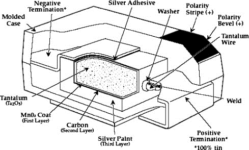
The tantalum capacitors is a special type of electrolytic capacitor. To make a tantalum capacitor, powdered tantalum is formed into a pellet through the sintering process. The pellet is submerged in an acidic solution and a DC voltage is applied, which creates an oxide layer over all the tantalum particles. This oxide layer ultimately forms the dielectric that separates the two electrodes. For the solid tantalum capacitors used in the demonstration, the pellet then receives successive coatings of manganese dioxide, graphite, and silver to form the cathode of the capacitor. This coated pellet is then packaged in a casing with external leads attached to the anode and cathode.
Much like aluminum electrolytic capacitors, tantalum capacitors offer immense capacitance values in very small packages. However, they are even more susceptible to over- and reverse voltage than their aluminum counterparts. With enough voltage, the dielectric breaks down and current begins to flow between the anode and cathode. The current flow can generate a good amount of heat, which can start an exothermic reaction where the tantalum and manganese dioxide act as a type of thermite. Yes, that capacitor, with enough energy, becomes a tiny thermite grenade.
The flame from an exploding tantalum capacitor is usually enough to ruin nearby circuitry. The worst part is that they often fail short. If you are using tantalum capacitors for power supply decoupling and a voltage spike causes a tantalum "event," the power and ground lines are then shorted together, which could ruin even more circuitry. Most literature calls for de-rating tantalum capacitors by 60%-70%. If you must use them, I would suggest de-rating by a lot more than that, such as 33% (e.g. if you are putting a tantalum capacitor on a 5V line, use one rated for 15V or more). In my humble opinion, you would do well to avoid tantalum capacitors all together.
De-Rating Rule of Thumb
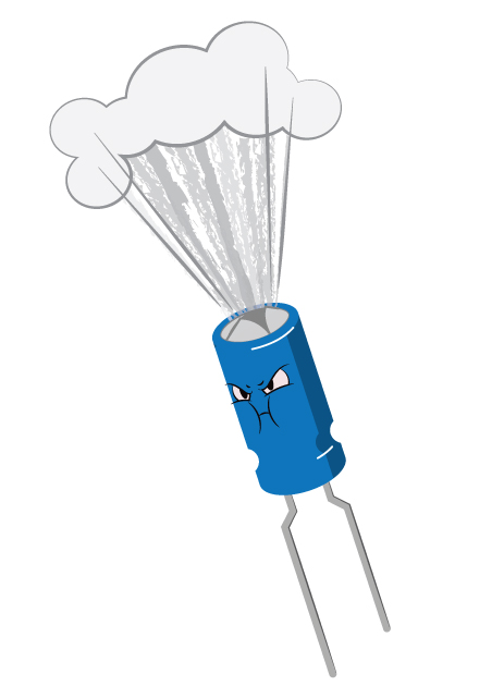
While people may argue about what is acceptable for de-rating capacitors, I would suggest using capacitors whose voltage rating is at least 2-3 times that of the expected voltage. For example, if you plan on decoupling a 5V power line, use a capacitor with a rated voltage at 10V or above. I recommend above 3x for tantalum (or better yet, don't use tantalum capacitors at all). Generally, it's a bad day if you see this:
