Enginursday - Stupid Eagle Tricks
Exploring some Eagle PCB internals.
As an engineer at SparkFun, it's a given that I'll be using CadSoft Eagle on a regular basis. When I started here in September, I considered myself proficient, having designed a number of PCBs over the years. But I've also come to better terms with Eagle, learned more of its inner workings, and picked up some additional tricks.
I thought there would be value in sharing some of what I've learned, and how it's been useful.
The Problem
I was designing a new board, and wanted to use a part that had been used on a previous board. I had the files for the original board, but I didn't have the library for the part. Ideally, I'd be able to extract the part from the schematic, and get it into the SparkFun libraries, without having to redraw it from scratch.
A part can get stranded in the schematic for several reasons - the most likely reason is that the original designer created the part in a local library, and never merged that library with the official ones.
(How to avoid using parts that aren't in the library to begin with? Map the libraries directory to only use the right ones - in my case, that's my local copy of the SparkFun-Eagle-Libraries Git repository. Don't forget to sync the repository frequently.)
Where to Begin?
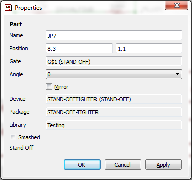
So how can you even tell what library a part is from? In the schematic or PCB editor, use the info tool.
Select the tool, then click on a part. The dialog that opens has a note indicating the library. In my case, it was something like "local-temp." Not a library present on my PC.
A Puzzle
So wait - if the library isn't present on my PC, how can I use parts from it?
This was one of the biggest Eagle mysteries to me at the time. I didn't have a clear picture of how Eagle handled libraries and components. I knew that if I modified a part in a library, I needed to use the "update" option to get the revised part to show up in boards that used it.
Some Insight
I asked SFUptownMaker about my situation, and he shared some useful information, which helped me piece together a much clearer picture of how Eagle handles the libraries.
In software terminology, Eagle uses a "copy by value" operation when a component is added to a design. The information for that component in the library is copied into the design files, in its entirety. Everything defined in the component editor comes along - the schematic symbol, all of the packages, and the data that binds the pins on the symbol to the pads of the package.
At the moment the part is added, it's essentially a snapshot of that part frozen in time at that instant. If the library changes, boards that use it have to explicitly acquire the changes, using the update command.
(This would be opposed to "copy by reference," in which the board files refer back to the library version of the data. If the library changed, the boards would pick up the change automatically. The board files then also become dependent on the library files. If I had a board file, but didn't have all of the libraries it used, it would be useless. Copy by value allows the board files to travel by themselves, independent of the libraries.)
Knowing how components trickle down from the library into the board files is useful, and explains how I got into this situation. However, I still needed to get information to flow backwards, uphill, from the board files to the libraries.
Lifting The Hood
This is where we have to take this well reasoned approach off-road, and use the tools in a way they weren't intended.
Eagle 6 marked the change from proprietary binary file formats to XML. XML is a more general derivative of HTML. Where HTML describes the layout of text and graphic elements on a webpage, XML is a generic means that can be used to specify any data - in this specific case, PCB related data. A specific dialect is defined using a schema, the grammatical rules that describe the statements used in a particular application.
CadSoft haven't published their schema, but by opening the files in a text editor (I'm using Notepad++, which has XML language support, and can roll up and match tags), it becomes apparent that the files use a reasonably clear dialect of XML.
Tags contain simple English statements, and they're organized sensibly, with different sections for each type of data stored. Each section is a list of a specific type of data contained within the file. If you're familiar with Eagle, you probably already have a sense of how different items relate - a device contains a symbol and packages, a schematic contains symbols and nets, and a PCB file contains packages and traces.
Back On Task
To return to the mission we're on here, we want to get a component that exists in a schematic, and move it to a library.
Looking in the schematic file of the component I'm working with, I have to work backwards a few steps, to get back to the library data.
- Using the name that was displayed in the info box, I search for that name. Towards the end of the file, I find an instance tag that contains the name.
- There is also a `part tag with the same name. This tag contains a reference to the library, and the specific device within that library.
- I search for the name of that library, and find a large tag in the
<libraries>section of the file. - There are several sections within the library the specify the data for the part. It's actually easier to make sense of the by working backwards.
- Towards the bottom of the library is a section for
<devicesets>. A deviceset corresponds to the device section of the library editor. It contains a number of gates. Each gate references a symbol, and a number of devices, each referencing a package. <Symbols>are the portion of the component used on the schematic. A device can contain multiple symbols, such as each of the gates contained within a logic IC.<packages>define the footprint of the part as used on the PCB - including the copper, holes, and silkscreen data. A device set may also contain multiple packages, perhaps for DIP and SMT variants of the same component.
- Towards the bottom of the library is a section for
To get the part from the schematic to the library, I open both files in separate tabs of my text editor. I copy and paste the deviceset tag, the symbols referenced by it's gate list, and the package tags that it lists. Each of these is placed at the bottom of the respective sections in the destination file - <devicesets>, <symbols>, and <packages>.
After cutting and pasting, I save and close the XML file. I then open it in the Eagle library editor. If I got any tags out of order, Eagle will helpfully tell me the line number that is causing the problem.
Sometimes it takes a couple of tries to get everything right. Opening the library in the editor appears to be a fairly decent judge as to whether the XML is properly formed.
I'm not especially confident that Eagle will behave gracefully if you have edited a file in both a text editor and Eagle itself. I'd imagine that one would overwrite the other. For safety's sake, I prefer to not have them both open simultaneously.
Epilog
While it makes my schematic-to-library part translation possible, there are some other advantages to using XML for storing the files.
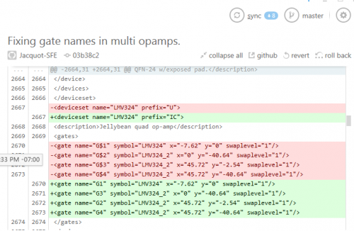
XML is great for storing PCB files in a text based revision control system, such as Git. At SparkFun, we're no longer just pushing opaque chunks of binary PCB data into the system - we can see meaningful deltas in the RCS, and even use a text editor to resolve merge conflicts.
It's not as great as a true graphical diff tool would be, but it's a lot more useful than just storing and comparing opaque binary blobs.
There are some situations where it's easier and more precise to manually edit the text of an XML file than it is to arrange items in a GUI.
Finally, since the file format is reasonably transparent, we can write new software tools around it. We have several in-house tools that take advantage of this, including the SVG importer.
Like a lot of things in Eagle, there may be more than one way to reach a result. I won't be surprised if someone responds to this post, and tells me that I just needed to look in menu X, or enter non-obvious command Y.

