Quad Fever!
Quadcopter fever is spreading through SparkFun! Of course we're going to hack them.
Quadcopter fever has blown through SparkFun. I'm not sure where it started, but suddenly, it seems like everybody is flying around a cheap little quadcopter.
The most popular model around here is the Estes Proto-X, a mere snip at $35-45US. It's small size makes it nice for goofing off around the office, but it definitely leaves something to be desired in the hacking arena. It can't carry much weight, of course.
-> 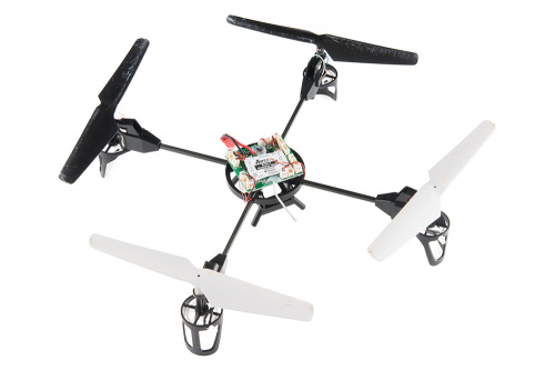
The Ares QX130, without the kinda dopey faring it normally wears <-
Jeff Branson, over in the Department of Education, found this sweet little beast: the Ares Ethos QX130. It's a bit pricier, but still quite reasonable at $99US. It has a couple of advantages, though: for one thing, it's just far enough up in the price/quality matrix to warrant replacement parts. Pretty much all the parts, from the rotors on down to control board and battery, can be purchased at reasonable prices from my local hobby shop. It's also pretty durable, as the terrible scuffs on the propellers above show.
-> 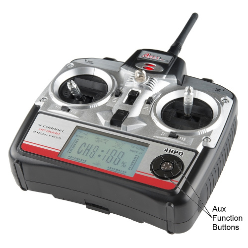
The controller that comes with the QX130, showing the auxiliary control buttons. <-
What really attracted me to it is that it has a sort of inherent hackability which lies in its built in accessories. Since it's closer to a toy than a serious machine for hobbyist fliers, Ares felt it necessary to provide a number of cute accessories: a bubble machine, a squirt gun, a rocket launcher, a winch, and a small camera. To control these devices, there are two "auxiliary" buttons on the controller.
The accessories themselves connect to the control board on the quad via some 1.5mm pitch shrouded connectors: two 4-pin headers and two 2-pin headers. So, of course, I have to ask: what do those connectors do, exactly? What's the pinout? What happens when I push the button on the controller?
Let's Hack!
To find out, I affixed my QX130 to a finely engineered test stand taped my QX130 to a peanut butter jar and powered it with a bench supply. Side note: at 3.9V, it draws 60mA before it's been paired with a transmitter and 120mA after pairing. The extra 60mA is due to the four LEDs mounted at the end of each a At 70% throttle, it's pulling about 2.8A; I didn't go higher than that because my bench supply has a 3A limit.
-> 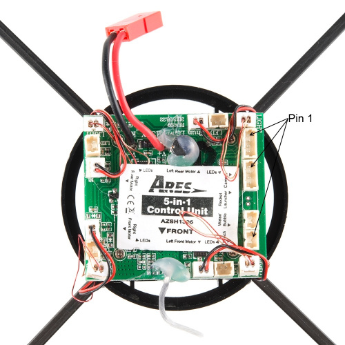
Close up of the controller board, showing my arbitrary pin 1 selections. Note the header names on the labels. <-
I decided to start with the rocket launcher port, for no discernible reason save a gut feeling that it might be a good idea. In the absence of any visible orientation marking on the connector or board, I'm going to declare that the pin closest to the camera header is pin 1.
A quick ohm-out with the meter suggests that pins 1 and 2 are connected to ground and pin 3 is connected directly to the positive rail of the battery.
Pin 4 is weird, though. When power is connected, it's low, but not stable. It starts about 200mV and decays downward as I observe the voltage. I'm going to guess that makes it a data pin, and probably not a push-pull drive. A 4.7k pullup to the supply pin causes it to idle high; when I press button 'A' on the controller (nominally the "fire one missile" button), I get a train of pulses. Button 'C' gives me a fairly long low pulse. In either case, I see a pretty wicked RC curve as the signal returns to VCC, and the pulse or train lasts as long as the button is held down.
The other connector I'm interested in is the camera connector. Maintaining the same pinout numbering as we did for the rocket launcher connector, we can see that pin 3 is ground, but none of the other pins ohm out to ground or the positive rail of the battery!
When powered, all three pins have a voltage present. Pin 4 is at 5.3V(!), and pins 1 and 2 are both at 3.3V. This is kind of weird; none of those is the voltage coming in from the battery, and one of them is, in fact, higher than the battery voltage! There's a nice big (relative to the rest of the board, anyway) inductor on the control board; I'm going to assume that it's a step-up regulator to power the camera from 5-ish volts. That leaves me interested in pins 1 and 2...what do they do when I push the buttons on the controller?
When you press button 'A' on the controller, pin 2 goes low for as long as the button is held down.. Button 'C' will cause pin 1 to go low. It looks as though the shortest period one can hope for is about 100ms, and the signal is very nice: I saw no bounces at the transitions.
Finally, let's look at the "Winch" connector. This one is really quite cool; neither pin connects to ground or VCC. However, an observation with the scope shows that the pins are, in fact, tied to an H-bridge! As long as the button on the remote is being held down, one of the pins will be high and the other will be a ~50% duty cycle 14kHz PWM. Keeping the same pin numbering, pin 1 becomes the PWM signal when button 'A' is held, and pin 2 when button 'C' is held.
I did look at the "Water/Bubble" header, but when I didn't immediately see anything interesting I moved on, since the other connectors provide more than enough interesting stuff to look at.
What's Next?
I'm not sure. A couple more people have indicated that they're planning to buy a QX130, so whatever I come up with, I'll have some local beta testers.
I've been thinking of a simple laser tag game that uses an IR receiver (or several of them, probably) to record "hits" from other quadcopters, and then cuts the battery power after some number of hits. If it happens, we'll certainly post about it!

