Enginursday: On the 555 Timer
For decades, the 555 timer has been a mainstay of hobbyist electronics. Is it time to retire this venerable little workhorse?
I recently had a brief Twitter dot com exchange wherein a less-experienced but still very capable "pro-am" electronics hobbyist was asking whether FETs could be driven directly by analog voltages. It turns out, she was hoping to control a motor's speed using a pot, without an Arduino in the mix, to create a high-power, variable-value resistor out of the FET.
Naturally, the first suggestion that popped up was "throw a 555 timer at the problem! Done!" I took issue with that, and I'm going to explain why here.
What is the 555 timer?
If you are relatively new to electronics, having come to it through Arduino, Raspberry Pi, or robotics, you can easily be forgiven for not knowing exactly what a 555 timer is.
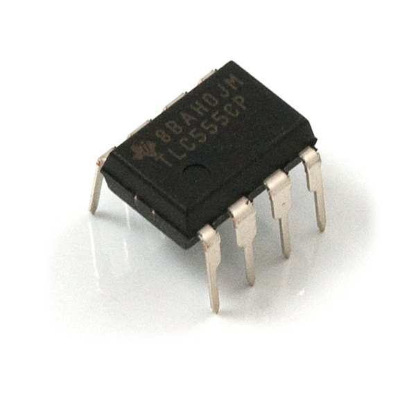
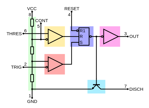
The 555 (or "triple nickel" as it's sometimes called) is one of the oldest integrated circuits around. It was introduced in 1971; commercial integrated circuits had only been on the market for about 10 years at that time. Unlike most early ICs, which typically had several copies of a single gate, it combines several different logical blocks into one package: two comparators, an S-R flip-flop, a buffer and an open-collector output.
The basic concept is fairly simple: by looking at one or more analog voltages (with the comparators on pins THRES and TRIG), generate a digital signal on a buffered output pin, and the inverse of that signal on the open collector output pin. Typically, the voltage(s) used for comparison come from one or more resistor/capacitor circuits; the time required to charge (or discharge) the capacitor(s) determines how long the outputs remain high (or low).
Applications
We typically divide 555 applications into two groups: astable and monostable (bistable is also possible, but as that's just basically ignoring a lot of the circuitry to use only the flip-flop, it's uninteresting and I won't discuss it any more).
Monostable configuration
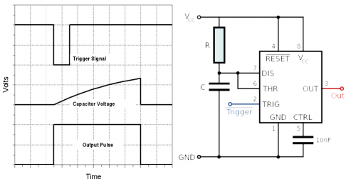
In a monostable application, an input signal is monitored for transitions. When a transition occurs on that input signal, the 555 circuit outputs a pulse of fixed length, regardless of the time between the triggering transition and the signal returning to its prior state.
Comparing the circuit diagram with the block diagram above, it's fairly easy to see what's happening. The DIS and THRES nodes are at VCC when the trigger occurs, as is the non-inverting input of the the lower comparator. That causes the output of the lower comparator to go high, triggering the SET input on the RS flip-flop. The BJT connected to the DISCH pin turns off, the output buffer turns on, and the capacitor C starts to charge through resistor R. When the voltage on the THRES pin exceeds 2/3 VCC (a fixed level, set by the three resistors in the block diagram above), the reset input on the SR flip-flop triggers, activating the BJT, draining the capacitor rapidly, disabling the output buffer, and setting up the circuit for the next triggering input.
I'm not going to get into the math of why, but the output pulse will be approximately 1.1RC, where R and C are in ohms and farads. Thus, a 10k resistor and a 10uF capacitor will yield about an 110ms pulse.
Where is this used? Anywhere we need to create a fixed-length pulse from an unknown input. Maybe you want a light to come on for five seconds whenever a button is pressed, or a horn to sound for five minutes if a door is opened. It's also used if we want to ignore rapid transitions on the input: any triggers received while the output pulse is active are simply lost. This makes it a good circuit for removing switch bounce from inputs to digital circuits.
Astable configuration
In the astable configuration, the circuit oscillates of its own accord, producing a square wave output of a frequency and duty cycle, determined by the selection of capacitive and resistive elements in the circuit below.
The cycle here is somewhat more complicated, but similar to, the monostable case, with the exception being that the TRIG and THR inputs are tied together to create a situation where one is true and the other false during some period of the oscillation.
Again, leaving out the deriving math, the frequency of the circuit is 1 / (0.693 * C ( R1 + R2 ) ) Hz, with C in farads and R1 and R2 in ohms. The high time is 0.693 * C * (R1 + R2) and the low time is 0.693 * C * R2.
We can immediately see that the high time is always going to be larger than the low time; thus, the duty cycle will always be greater than 50 percent. That can be mitigated by putting a diode in parallel with R2; this changes the equation for the high time to R1 * C * ln((2Vcc - 3Vd)/(Vcc-3Vd)) where Vd is the forward voltage of the diode you used. Of course, now your duty cycle is tied to Vcc and will vary if that's not stable...say, if it's derived directly from a battery.
Finally, if you want to adjust the duty cycle on the fly, you'll need to replace one of the resistors with a potentiometer. But, tweaking just one of the resistances will change the frequency as well as the duty cycle!
Confused yet?
In defense of the 555
So, in defense of the 555 based solutions above, they're cheap. We sell 555 timers for $0.95US; if you're willing to buy more of them, or dig through datasheets to make sure you're getting the one you want, they can be had for somewhat less from the major online parts distributors. The passives are pennies, although you need to lay out a few bucks to get a good resistor assortment and capacitor assortment to ensure that you'll have the various values you need to cover most situations. Overall, your average 555-based solution is likely to cost near $1US, give or take.
Of course, if you put any kind of value on your time and frustration, this is a pretty expensive solution. You've got to do all the math I spelled out above and try to tweak the resistor and capacitor values that you actually have on hand to produce the results you're looking for; there are a number of different online calculators available, but even with those, you can be off by 10 or 20 percent, or more. Plus, if you discover that you need a different frequency, you've got to recalculate your values! And don't even get me started about temperature coefficients, power supply rejection ratios, and part tolerances!
There's got to be a better way!
And there is! Several, in fact.
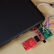
- The Arduino Pro Mini - For $10, you can replace the entire circuit with an Arduino Pro Mini. The code to duplicate the function of either of the above circuits is very simple, and can be easily modified to change the duty cycle and frequency of an astable circuit or the pulse length of a monostable circuit. Not only that, but you get a "free" processor to do other stuff with, AND you can emulate several 555 circuits with one processor!
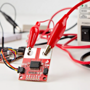
- The Servo Trigger - For servo-based problems, the servo trigger is a good solution. While a 555-based solution gives you the ability to set and hold a position, usually by adjusting a potentiometer, the servo trigger allows you to react to external triggering events, slewing from one position to another and back automatically. It's much more expensive, at $20, but if you want to avoid programming and have a "one-and-done" type of solution, it's hard to beat.
- The ATTiny85 - For size, it's hard to beat the ATTiny85. You'll need a programmer; we sell one designed specifically for this part. It's also (once you have the programmer) the cheapest solution; at $2.84US, it's not much more than the 555 and the passives needed to make the circuit work. It also has the same benefits as the Arduino Pro: you can emulate several 555 circuits with one chip, it's far easier to change the frequency and duty cycle, and you have a processor that can be used to do some other stuff if you need it.
Your mileage may vary, no purchase necessary, void where prohibited by law
Another advantage of the two programmable options here is that learning them adds a huge and extremely versatile tool to your bag of tricks. Getting good at using a 555 timer isn't terribly portable; to go beyond simply plug-and-chug calculating values requires a pretty solid electronics background. If you already know how to program, extending it to implementing a 555 timer's functionality is fairly easy; if you don't know how to program, you're better off spending the time you'd be sweating over capacitor and resistor values learning to program.
Old habits die hard, and using the 555 timer in electronics is one of the oldest habits there is. There are no doubt niche applications where the 555 is the only way to go, but 99 percent (or more!) of the time I see them recommended to a hobbyist, that hobbyist would be way better off using some kind of programmable solution.
