Adventures in Science: Level Up Your Arduino Code With External Interrupts
Let's continue digging deeper into Arduino to see what's really going on with registers.
Last time we looked at Arduino code, we examined how registers worked in the ATmega328P. We continue peeking under the hood to see how to set up external interrupts using direct register writes.
An interrupt is anything that can stop the main execution thread of a program and cause the processor to perform some action before returning to that main thread. In the case of external interrupts, something like a button push can be configured to cause this brief pause to allow some other piece of code to run.
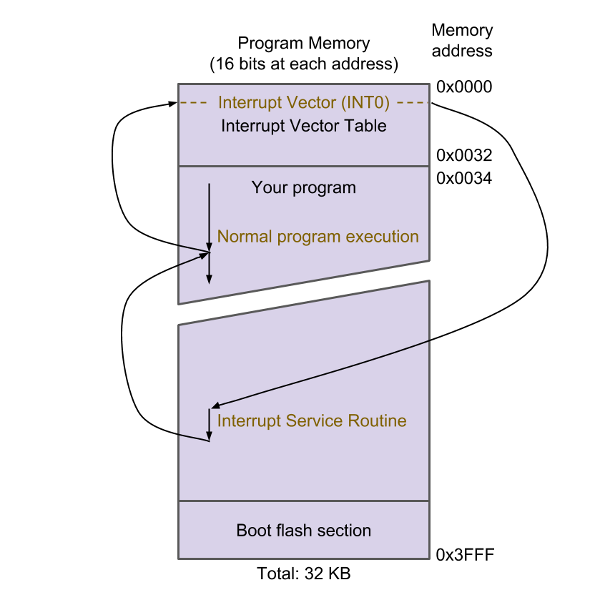
In the ATmega328P, program memory is divided up into three main sections:
- Interrupt Vector Table (IVT) --- Tells the processor where to jump to find the interrupt service routine (ISR) for each interrupt source (e.g., Port D, Pin 2 falling edge).
- Program Space --- This is where your main program lives. Any ISRs you write will also live here.
- Bootloader --- Optional section of code that runs first on a microcontroller that allows you to send new programs to it through nontraditional means (e.g., over the UART port instead of the ISP port). It can be configured to do other things, but being able to load programs over UART is what makes Arduino work so nicely.
When you give power to (or reset) your ATmega328P, the very first instruction that's loaded is at program memory address 0x0000. This just happens to be the RESET vector. Usually, the only instruction there is a jump command to another place in memory (usually 0 x 0034 --- the start of your program space). Your program begins executing sequentially from there. Part of the setup code might be telling the processor that you are open to an external interrupt when Port D, Pin 2 (also known as interrupt source "INT0") experiences a falling edge (logic HIGH to logic LOW).
Note that you generally need three things to happen to have the interrupt trigger:
- Global interrupts must be enabled (in AVR, this is accomplished with the
sei()function). Note that global interrupts are enabled by default in Arduino. - The individual interrupt must be enabled (usually by setting a bit in a particular register associated with that interrupt).
- The interrupt condition must be met (e.g., a falling edge on a particular pin).
Once all three of these conditions are met, the interrupt will trigger. Execution on your main program will stop, any state variables or numbers the processor was working on are saved to memory, and execution jumps to the IVT. Which entry in the table it moves to is based on which interrupt triggered. For example, a falling edge on Port D, Pin 2 is the INT0 interrupt, so execution will jump to address 0 x 0002 (see the Reset and Interrupt Vectors table in the ATmega328P datasheet).
Often, only a single instruction will reside at the interrupt address. This is normally a jump command to somewhere else in program memory, which is where the ISR resides. The memory location of the ISR is known as an "Interrupt Vector." So, our processor will jump to the ISR, perform whatever instructions it finds there, and then jump back to the main program to pick up where it left off (restoring any saved variables it might have previously stored).
External interrupts are great for responding to things like button pushes in a timely fashion or waking from a sleep state when a sensor has data to be read.
How else have you used interrupts? Why do you find them so important in microcontroller development?
