Enginursday: Sparking Creativity in Troubleshooting
Let's talk about a PCB design error and troubleshooting the root cause.
My prototype PCB design came in and is all built up and is ready for testing. I connect the board to my PC, but sadly, no signs of life. I measure the resistance between the supply voltage rail and ground, and I get 0 ohms. Hmmm well that's not ideal, let's see what's going on.
The way we build prototypes here at SparkFun is we order a few PCBs and a solder paste stencil, and then hand place the components before reflowing the board to melt the paste. Prototypes allow us to not only test the PCB design, but also to test our paste stencils and make sure we're not adding too much solder (which could short components or pins together), or too little (which could prevent a part from making a secure electrical/mechanical connection).
The design has a new QFN part with an exposed pad underneath, which is connected to ground. My first thought was the stencil used too much paste and the paste is shorting my 5V rail to ground. I de-soldered the part, wicked off as much solder as I could and did a visual inspection to make sure I couldn't see any problems. I took another resistance measurement, and still, 0 ohms.
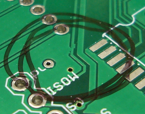
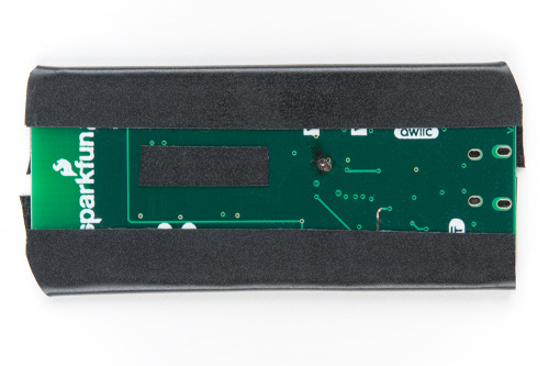
I pulled up the design and removed every part that was connected to the 5V rail, but still, 0 ohms. I grabbed one of the extra boards that wasn't populated and measured the resistance, and even the blank board has a short. I started to do a visual inspection of the board, looking for problems like this:
I looked over both sides of the board, without finding anything. This is a four-layer board though, and most of the copper for the 5V rail is on the inner layers. I checked the design again, and looked at the Gerber files to see if it was a design error or a manufacturing error.
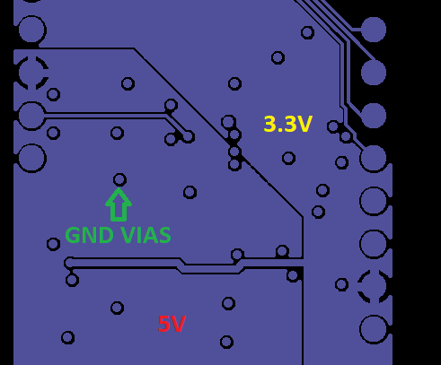
On layer two, I have my 5V and 3.3V power rails, and on layer three I have my ground, using vias to bring power and ground to the top and bottom layers. The only thing I can think of is a whisker shorting to a ground via from the inner layer. Without specialized equipment like an X-ray, I can't do a visual inspection, so how can I test that?
POWER!
If you think of how a fuse works, you have a large amount of current passing through a wire. As you increase the current, the wire starts to heat up; add too much heat, and the wire melts and becomes an open circuit. Ideally, I'd like to be able to still use the boards if it's a single whisker, so I connected our 20A Mean Well power supply. One hundred watts should be enough right? Maybe, but the short circuit protection of the supply works too well, and I wasn't able to make any sparks.
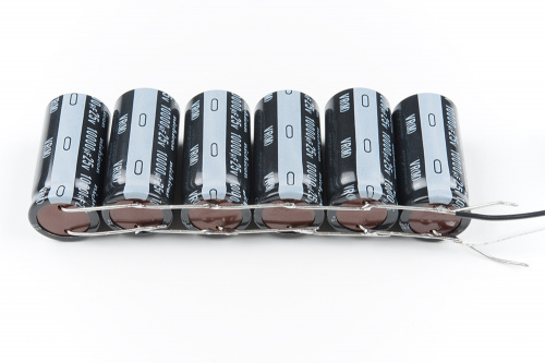
Since it's the current that I need, I soldered together six 10,000uF/25V in parallel to create a 60,000uF short finder. After charging the capacitor bank to 5V I connect the leads to 5V and ground, keeping the wires short to minimize power loss in the cables. After a small spark, I measured the resistance again and this time I saw ~1MΩ. It's not perfect, but it should be good enough.
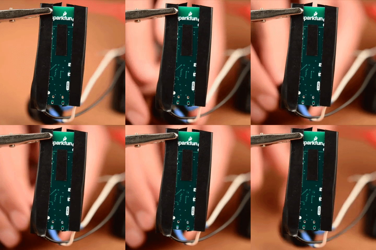
Because we have a few copies of the board, I was able to film clearing the short. The first time however was a bit more dramatic, with a small flame of 2-3mm in size, that burned itself out pretty quickly, but it made it obvious where the short was, as seen below.
