Enginursday: Two-Wheeled Robot Precision Driving with Encoder Feedback
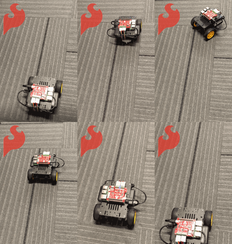
Using encoder feedback to control two DC motors, this robot is self-correcting!
My challenge seemed simple enough: I wanted to make a two-wheeled robot drive a straight line using feedback from a set of wheel encoders. Little did I know that this would open the doors into the vast world of PID motor control!
Background
Prior to starting this project, my experience with two-wheeled desktop robots had been pretty minimal. I had helped teach a few classes to educators using the SparkFun Redbot - this involved helping our participants get set up and coding challenges such as line-following and driving a pattern. We used manual “trial and error” to match motor speeds, and then used delays to control distance traveled. Although this is a wonderful introduction to coding and robotics, it’s not quite ideal for driving a very straight line and/or a precise distance. Seeing these challenges in the classroom planted the seed for this project. I knew there had to be a fun way to incorporate some high resolution encoders to augment driving control!
Hardware and approach
After researching many options, I ultimately decided to go with the Qwiic Motor Driver, a set of geared DC motors that included quadrature encoders, and a Raspberry Pi 4 as the master brain.
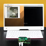
Using a Raspberry Pi 4 as the controller had two very handy benefits: First, my program would be written in Python, and second, I was excited to have the capability to adjust the code and see streaming data in real time via a Wifi and VNC viewer.
Choosing a method to read the encoders was a bit of a longer story. My previous experience with encoders involved user interfaces and turning knobs. This involved a lot of interrupts firing to keep track of the pulses and ultimately a “position from zero.” Although it would be possible to wire up the encoders directly to GPIO on the Raspberry Pi, I wasn’t interested in bogging down my Python program with interrupts.
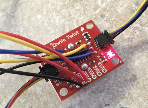
I ultimately found the SparkFun Qwiic Twist, and decided to do something similar. The Twist utilizes an ATTiny84 to handle reading a single encoder. It keeps track of a count variable that is then easily read from the Twist via I2C. I chose to use this design and firmware as a starting point.
I stripped out the LED and button control and was able to utilize a second interrupt and more GPIO to read a second encoder. Wahoo! I had my dual encoder reader, and my counts would be available on the I2C bus!
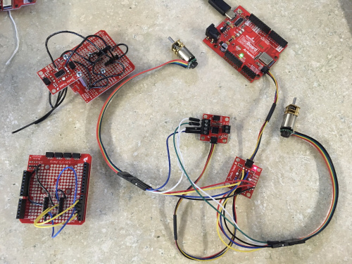
To modify the Twist firmware I actually developed with an Arduino Redboard Qwiic first (acting as an alternative to the ATTiny84). This allowed me to use the UART port for debug while finishing up the modifications to the firmware (most importantly, adding support for a second encoder).
Let’s drive!
After wiring everything up, I simply set the motors to the same “power” and watched what happened. Wow, motors can vary a lot! My robot was turning sharply to the left, meaning that the right motor was actually out-performing the left motor by a lot. Now it was time to jump into some encoder counts and see if we could correct this difference!
This is the portion of my code that commands driving the straight line:
for i in range(0,300):
    count12_delta = myEncoders.count1 - (-myEncoders.count2)
    error_change = count12_delta - prev_count12_delta
    motor_speed_correction = count12_delta
    motor_speed_correction *= P_gain #proportional adjustment
    motor_speed_correction += (I_gain * error_change) #integral adjustment, looks at the change in error, if it gets smaller, than slow down the correction
    left_motor_speed -= motor_speed_correction
    myMotors.set_drive(L_MTR, L_FWD, (left_motor_speed))
    print("1:%d \t2:%d \tLS:%d \tRS:%d \tCD:%d \tEr:%d \tMC:%d" % \
                  (myEncoders.count1, -myEncoders.count2, left_motor_speed, right_motor_speed, count12_delta, error_change, motor_speed_correction))
    prev_count12_delta = count12_delta
As you can see here, I'm using a very simplified quazi-PID control system. You may also note that I'm not yet incorporating a derivative correction (this may come as a later improvement).
To start, I look at the delta between each count, and then deciding whether to adjust the left motor by a specific amount (motor_speed_correction). The correction is actually set initially as just the difference in counts, and then my proportional gain is amplifying this by a set gain (P_gain). The integral adjustment comes from looking at the change in the error. If the change in error is getting smaller, then it adjusts the amount of correction.
The turn around portion of the code looks like this:
for i in range(0,300):
    count12_delta = abs(myEncoders.count1) - (-myEncoders.count2)
    error_change = count12_delta - prev_count12_delta
    motor_speed_correction = count12_delta
    motor_speed_correction *= P_gain #proportional adjustment
    motor_speed_correction += (I_gain * error_change) #integral adjustment, looks at the change in error, if it gets smaller, than slow down the correction
    left_motor_speed -= motor_speed_correction
    myMotors.set_drive(L_MTR, L_BWD, (left_motor_speed))
    print("1:%d \t2:%d \tLS:%d \tRS:%d \tCD:%d \tEr:%d \tMC:%d" % \
                  (myEncoders.count1, -myEncoders.count2, left_motor_speed, right_motor_speed, count12_delta, error_change, motor_speed_correction))
    if(myEncoders.count1 < -575):
        break
    prev_count12_delta = count12_delta
It is very similar to the straight line command, however I now flip the direction of the left motor and took the absolute value of its count. Then I also added in a check on count1 to break out of this for loop once the desired rotational travel has been reached. In this case, the value 575 seemed to be about a perfect 180-degree turn.
Going further
I have two things I'd like to try next:
- I intend to look at each motor's speed (rather than just looking at the current count value). This would allow me to try and match each motors speed individually. I gave it a shot in the Python code, but I would really love to offload the speed calculations to the ATTiny84, so that will involve modifying that firmware again.
- I would also like to improve upon my PID method. Currently, I am actually only incorporating the proportional and integral gains, so I would like to modify this eventually to include a derivative correction.
Do you have any experience with driving similar desktop rovers? Any ideas for improving my system would be much appreciated. Thanks, and happy driving!

