Enginursday: Doing Away with Delay() in a Different Way
A different approach to the problem we solved last week
Last week, my esteemed colleague MTaylor explored a solution to scheduling periodic tasks on Arduino. In the comments, several people mentioned that a Real Time Operating System (RTOS) might be a more flexible and generic solution to the timing and scheduling problem.
I've done a lot of programming with RTOS on larger microcontrollers, like the Motorola 68000 and various ARM7 chips, but hadn't yet used one on an 8-bit micro. This seemed like an opportune time to do a survey of RTOS, hopefully finding one that could fit on small microcontrollers, and that wouldn't take a lot of effort to get working. My goal was to have something that I could use on a RedBoard or ProMini, both of which are based on the Atmel ATMega328P, a member of the AVR family.
I've done surveys like this in the past, and my findings ranged between disappointing and frustrating. It wasn't easy to find an RTOS that ran on the AVR, wasn't broken or incomplete, was well documented, and was compatible with the compliers and debuggers I had available
This time around, however, I found exactly what I was looking for: Bill Greiman (the guy behind the SdFat library) has ported FreeRTOS to work as an Arduino Library, with support for both AVR and ARM based boards.
It seemed to meet my requirements: I've got the Arduino IDE, and from past experience, I knew FreeRTOS is mature, well documented and reasonably full featured. If you're adventurous, he also has Arduino-library versions of ChibiOS and NilRTOS.
Installing and Loading
Moving from plain Arduino to an RTOS is a big conceptual step -- big enough that a single blog post isn't going to be a comprehensive introduction. Rather than getting deep into RTOS therory or application design, let's jump in and get an RTOS working, then examine some code that uses its facilities.
For these examples, I'm using a RedBoard and Arduino 1.6.5.
To install the FreeRTOS Arduino library:
- Get the zip file from GitHub.
- Install the library by copying the folder from /libraries/FreeRTOS_AVR to your local Arduino library directory. On my PC, that's
C:\Users\byron.j\Documents\Arduino\libraries. - Open the Arduino IDE. From the file menu, select
file->examples->FreeRTOS_AVR->frBlink - Build and load the sketch.
That's really all there is to it. The result should be that the pin 13 LED blinks about twice a second.
A Quick Tour
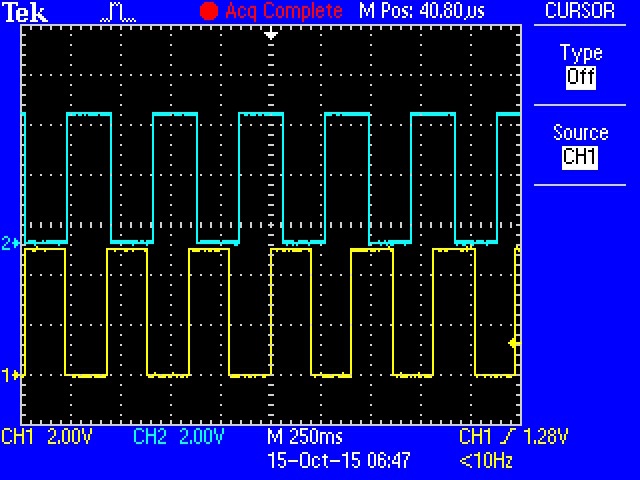
As a quick example of RTOS programming, I've adapted MTaylor's 3-channel blinker example. For the sake of demonstration, I've changed a couple of things. I'm only running two timed blinkers, rather than three. I've also assigned each of them its own LED, rather than sharing a single LED among them. The LED on pin 13 flashes every 200 milliseconds, and I've added a second LED on pin 12 that toggles every 210 milliseconds.
/******************************************************************************
FreeRTOS timed blink example

Byron Jacquot @ SparkFun Electronics>

Porting Marshall Taylor's out-of-synch blinker example
to an RTOS, to show off basic features.

Resources:
Requires Bill Greiman's port of Free RTOS to Arduino
https://github.com/greiman/FreeRTOS-Arduino

Development environment specifics:
Arduino 1.6.5
SparkFun RebBoard with additional LED on pin 12.

This code is released under the [MIT License](http://opensource.org/licenses/MIT).
Distributed as-is; no warranty is given.
******************************************************************************/

#include <FreeRTOS_AVR.h>

// The LED is attached to pin 13 on Arduino.
// Plus another LED on 12
const uint8_t LED1_PIN = 13;
const uint8_t LED2_PIN = 12;

/*
 * First blinker does 200 msec on, 200 msec off.
 */
static void ThreadLED1(void* arg)
{
  pinMode(LED1_PIN, OUTPUT);

  while (1)
  {
    vTaskDelay(200);
    digitalWrite(LED1_PIN, HIGH);
    vTaskDelay(200);
    digitalWrite(LED1_PIN, LOW);
  }
}

/*
 * Second blinker does 210 msec on, 210 msec off.
 */
static void ThreadLED2(void* arg)
{
  pinMode(LED2_PIN, OUTPUT);

  while (1)
  {
    vTaskDelay(210);
    digitalWrite(LED2_PIN, HIGH);
    vTaskDelay(210);
    digitalWrite(LED2_PIN, LOW);
  }
}


void setup()
{
  portBASE_TYPE status1, status2;

  Serial.begin(9600);

  // create two parallel LED tasks at priority two
  status1 = xTaskCreate(ThreadLED1, NULL, configMINIMAL_STACK_SIZE, NULL, 2, NULL);
  status2 = xTaskCreate(ThreadLED2, NULL, configMINIMAL_STACK_SIZE, NULL, 2, NULL);

  if ( (status1 != pdPASS ) || (status2 != pdPASS)) {
    Serial.println(F("Creation problem"));
    while(1);
  }
  // start scheduler - should never return
  vTaskStartScheduler();
  Serial.println(F("Scheduler Returned"));
  while(1);
}

//------------------------------------------------------------------------------
// WARNING idle loop has a very small stack (configMINIMAL_STACK_SIZE)
// loop must never block
void loop()
{
}
If you put a second LED on pin 12 (I inserted mine right into the header, with the anode on pin 12, and the cathode on the ground pin just past pin 13), and load this sketch, you'll get an out-of-sync blink pattern, akin to desynchronized automotive turn signals. They'll appear to blink together for a moment, but after a while, they drift apart.
A Different Structure
Normally, when we add a library to an Arduino sketch, we pick up some new features or functionality, structured for the simple cooperative taking model of Arduino. However, when we use an RTOS, we need to change the way the application is structured.
Let's look at the code above a little more closely, starting at the bottom and working our way up. The new structure will reveal itself.
loop()
//------------------------------------------------------------------------------
// WARNING idle loop has a very small stack (configMINIMAL_STACK_SIZE)
// loop must never block
void loop()
{
}
The loop() function is at the very bottom of the file...and it's empty! The place where we're usually doing the work of an Arduino sketch isn't actually doing any work. As mentioned above, the structure of an RTOS application is very different from a regular Arduino one.
setup()
void setup()
{
  portBASE_TYPE status1, status2;

  Serial.begin(9600);

  // create two parallel LED tasks at priority two
  status1 = xTaskCreate(ThreadLED1, NULL, configMINIMAL_STACK_SIZE, NULL, 2, NULL);
  status2 = xTaskCreate(ThreadLED2, NULL, configMINIMAL_STACK_SIZE, NULL, 2, NULL);

  if ( (status1 != pdPASS ) || (status2 != pdPASS)) {
    Serial.println(F("Creation problem"));
    while(1);
  }
  // start scheduler - should never return
  vTaskStartScheduler();
  Serial.println(F("Scheduler Returned"));
  while(1);
}
Above that is setup(), and there's a little more going on here. Like any regular sketch, this initializes things used by the sketch -- most notably, the two calls to xTaskCreate(...). These calls inform the RTOS of functions that actually do the work. The first parameter of each of these is the name of the routine that implements the timed LED blink, ThreadLED1 and ThreadLED2, respectively. After creating the tasks, setup calls vTaskStartScheduler(). If all goes according to plan, this call will never return.
The LED Tasks
static void ThreadLED1(void* arg)
{
  pinMode(LED1_PIN, OUTPUT);

  while (1)
    {
        vTaskDelay(200);
        digitalWrite(LED1_PIN, HIGH);
        vTaskDelay(200);
        digitalWrite(LED1_PIN, LOW);
    }
}
Each LED is controlled by its own function, ThreadLED1 and ThreadLED2. Aside from the pin it's controlling, and the time values used, these tasks are identical. They configure their respective pin as an output, then enter an endless loop, pausing and changing the LED state.
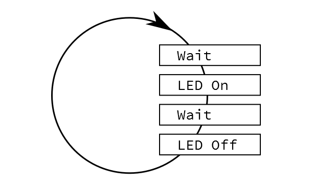
Reading these functions, they are straightforward and understandable: Wait a while, turn the LED on, wait a while again, turn LED off, repeat. The real trick is to make the waiting less expensive.
The whole point of this exercise has been avoiding the Arduino delay() routine. Delay is problematic because calling it keeps the system busy, counting down the specified time. It doesn't do anything else in the meantime. But what if it could?
Instead of delay(), the LED threads call the FreeRTOS function vTaskDelay(). From the perspective of the function, it's pretty similar, but behind the scenes, it allows other things to happen without our LED blink routine having to know about it. When vTaskDelay() returns, the specified time will have elapsed. The xTaskCreate calls told the RTOS about work to be done, and the RTOS figures out when to do it.
You can think of the LED threads as running independently, in parallel. They don't have to worry about anything external. This is a simple example of multitasking, a common feature of RTOS. Adding another LED could be as simple as writing a third function, and starting up a third task.
Going further
Again, there's a lot more going on inside an RTOS than I can cover in one short blog post. Hopefully I've peeled the tarp back far enough that you're ready to explore a bit on your own.
FreeRTOS has a lot of documentation online.
- First, I'd recommend looking over their naming conventions. Their functions and variables look like they're prepended with alphabet soup, but it's actually an application of Hungarian notation, which makes more sense once it's been explained.
- Similarly, there are a number of compiler macros used by FreeRTOS, which are explained here.
- There's documentation of the routines and features of FreeRTOS in their API Guide.
From there, I'd progress through the other examples in Mr. Greiman's library, which demonstrate some different features and instrument some interesting circumstances.
Useful Stuff to Know
Moving from cooperative, single-tasking Arduino to an RTOS involves a different approach to structuring applications. There are bound to be some sticking points.
- The first sticking point is RAM.
- The RTOS approach requires more RAM, as each task needs RAM for its own stack. I generally see this as a small price to pay for being able to write more efficient and better organized code. Moving from the RedBoard to an Arduino Mega 2560 quadruples the amount of RAM, easing that restriction.
- You can also check the amount of free RAM on the system using the
freeHeap()anduxTaskGetStackHighWaterMark()system calls. There's a good example of these in the frBlinkPrint example sketch. - You'll notice that the
F()macro is used on strings in the Serial.print() calls of many examples, so that strings are stored in flash memory, rather than getting copied into RAM when the processor boots.
- The compatibility of existing Arduino libraries needs to be evaluated. Most Arduino libraries use a cooperative-polling approach, which might conceal busy-wait situations.
- An RTOS is a pretty sophisticated piece of code, and as such, it's hard to debug in the Arduino IDE. Serious debugging calls for more serious tools. Atmel Studio 7 adds the ability to create projects from *.ino files. I haven't had time to try it yet...maybe that will be my next blog post.

