Enginursday: The Hot Seat
The long SparkFun tradition of mild sadism in the name of comedy continues!
If you've been following the antics of the SparkFun team for any amount of time, you'll know that we're a slightly sadistic bunch. We love each other, but we also love to be a little mean to each other sometimes. Classic office shenanigans like electro-Jenga, the horn box and Tim's finicky monitor have brought a great deal of joy to our surroundings, and in the spirit of these past glories I present to you "The Hot Seat."
The Hot Seat uses our new conductive adhesive copper tape and a hacked electronic fly swatter to deliver a shock to the back of the player's legs when they fail to maintain a steady hand on the wire maze attached to the chair arm. That, of course, makes them worse at the game ... and so on.
The shock is on the order of hundreds of volts; the longer your failure is (i.e., the longer the wand touches the course), the worse the shock. The position of the electrodes makes it unlikely that anything fragile will be affected; the current path is short and through skin only.
If you're interested in how this thing works, read on. Otherwise, just watch the video, again and again, and remember that, since every person in it is a volunteer, you can take as much pleasure in our discomfort as you like.
Now, on to the gritty details. I'm fascinated by things like this fly swatter. Built and shipped from China to be sold for $4 ... it's amazing! I had a fair idea of what would be going on inside, but let's take a look.
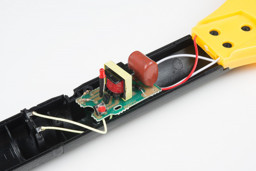
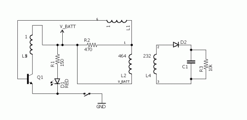
As you can see, the board is really simple. Single-sided unmasked unsilkscreened, with only a handful of components. Here's the schematic as I've reverse-documented it.
You can see that the board is basically just a BJT switch that allows a large dump of current through the low-voltage windings of the transformer. On the high-voltage side, we expect a proportionally smaller current to flow (the "turns" labeled on the schematic are, in fact, the ratio of resistance of one set of windings to the other; I'm making the assumption that the wire gauges are the same) but to see a proportionally higher voltage develop across the capacitor. There's a blocking diode to prevent C1 from discharging back across the coil when a steady state is reached on the LV side.
The circuit is really simple, which I'd expect for a $4 item. It's kind of cheesy (the transistor gets pretty hot if you hold down the button too long), and the construction is shoddy, but it works.
I've played around with this a bit; replacing the button (or rather, paralleling the button) with any other break/make circuit works fine for triggering the device. I've used an NMOSFET as a switch for a microcontroller-based device with this, to great effect.
We had a lot of fun making the video, and the project; I hope you enjoyed watching!


