Power Supply Protection
What is the best way to protect electronics against reverse polarization?
When designing a board, power is always a concern. Not matter if the power supply is batteries or a wall wart, you have to consider how the user is going to attach the power supply. Given the opportunity, we have to assume that power will be hooked up wrong. This brings up the discussion of 'reverse power protection'.
How would you design a circuit to withstand having the power applied backwards?
If you've ever plugged in a chip backwards, a wallwart backwards, or shorted VCC to GND, you know what we're talking about. And if you haven't hooked something up backwards, you're not human.

Chris Anderson recently brought up this discussion with me over the ArduPilot. This small board is a good example of the different options available. You can see the small BAS16 diode highlighted in the above Eagle PCB layout. This small diode is designed into the product to protect against reverse polarization. If someone hooks power up backwards, the diode fails to forward bias and the board simply doesn't turn on, protecting it from damage.
1) Inline protection diode: The problem is the forward voltage drop of the diode.
Cheap diodes have a theoretical 0.7V drop. So if you hook 5V up to the board, you'll get 5-0.7=4.3V delivered to the board. In practice, the forward drop of the diode is actually a bit lower (0.5V) and there are specialty diodes available that have even lower forward drop (germanium?). This all works great if your incoming power is 2-3 volts higher than your output, but if you're running a 5V board from a 5V source, the diode will drop the voltage to your system down significantly.
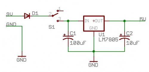
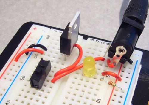
2) No protection: This is my favorite because it's so dangerous!Do we really care? Can the electronics survive if we put the batteries in backwards? If you're designing your own board, running without any protection can very questionable. Many current electronics can survive reverse power without any ill effects, but if you're playing with any part worth more than $5, I'd get something on the board to protect my parts. The beginning embedded electronics tutorial #1 will show you how to create a good bread-board power supply. At the very least, I recommend large, clear labels on the power pins:

Checkout the Eagle DFM tutorial for more information about labeling your board.

LDO Voltage regulator with two 10uF tantalum capacitors
