Enginursday: Prototyping 3D Parts
A look at the design considerations of rebuilding the fiber optic mounts for my light suit to accommodate new fiber optics and LEDs
So we just got this neat little 3D mouse up here in Engineering, and I'm finding just about every excuse to use it. I've been needing to perform some serious redesigns on a few components of my fiber optic light suit, mainly the fiber optic mounts.
They're a tad too large for my liking, and I'm also changing the fiber optic and LED that I'm using, so I'll need to devise a new way to get that light into the fiber. These original mounts also ended up failing on the printer quite a few times, and when they didn't fail, they didn't perform how I had originally envisioned them to perform, so we go back to the drawing board until our vision comes to fruition!
Version 2.0
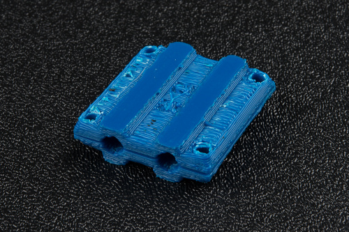
So let's go over the issues with the original part that I'd like to remedy (Version 2.0, pictured below).
First of all, sometimes the scaffolding that holds up the left and right sides of the part ends up sagging under the heat of the printer, resulting in a part that won't hold an LED or fiber. To fix this, I'm going to change the design to get rid of scaffolding altogether; this way, there will be nothing to warp. This will also partially fix the second issue with the part --- it requires too much finishing after I take it off of the printer. Without any scaffolding, I'll have nothing that needs to be peeled off of the part. In the end this also makes for a much smoother and better-looking part. The final issue I was having was that the part would sometimes crack under the stress of being clamped down in the fiber optic. This can be fixed with a simple change of infill, so more of the inside of the part is full of plastic.
Print, Fix, Repeat
Getting a part just right often takes a few iterations, as the printer (or at least the Taz 6 I print on) has a little under a millimeter of error, which doesn't sound like a lot until you start printing parts with itty-bitty details. What I will usually do is adjust multiple features of the part at once, but for the purposes of this post, I'll only change one thing at a time from one version to the next.
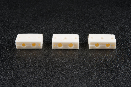
Shown from left to right above are versions 2.01, 2.02 and 2.03. In these versions, I shortened the tube that holds the fiber and adjusted its size to fit my new fiber optic. In 2.01, the hole was too small. I overadjusted in 2.02, and the hole was too large. In 2.03, I found the Goldilocks zone, and the part grips perfectly. It's a little tough to notice in the photo, but each half of 2.03 is nearly perfectly flush with each other. This is because I used a rasp to smooth this face of the part to allow a tighter fit.
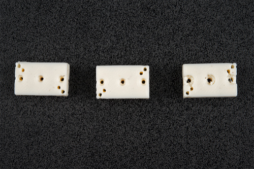
Now, I'd like to change the screw holes in order to allow for countersunk screws to keep the profile of the part free of bumps from hardware. In versions 2.04--2.06, shown below from left to right, I was adjusting hole sizes and countersink depth in order to get the screw holes perfect.
I ran into an issue here of a lack of support structure in my countersinks. Since the countersinks are on the bottom face of the part, the printer occasionally makes little beads of plastic around the edge of the hole due to a lack of support structure. This makes my countersink a bit of an imperfect hole, and the nut doesn't sit perfectly without a careful drilling out of the countersink. However, I fixed the problem of a serious amount of hardware hanging off of the part. I'm going to go ahead and call it a success, as I've reduced the finishing of the part to only two steps: the rasp on the faces that are in contact with each other, and milling out the countersink.
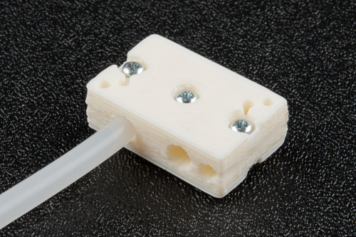
I'll have to do a few more iterations once I receive the LEDs and boards to ensure they attach and fit correctly, but PCB manufacturers do occasionally take a little bit of time to make boards, so that update will come in time. The final version that I'm currently happy with is shown below.

