Enginursday: Cardboard Circuits
Affordable, consumable, single-layer PCB design!
Maker education is something very close to my heart. It is a gateway to STE(A)M fields and a great way to learn creative problem solving. Two of the traditional challenges --- barriers to entry --- of bringing electronics into maker education are cost and accessibility.
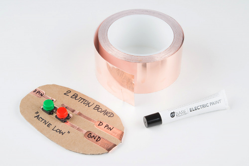
This week I have been experimenting with different ways to drastically reduce cost and increase accessibility with custom circuit stickers and cardboard circuits that don't remove the circuit design in the process of exploration and play. The idea for cardboard circuits came from DIY Electronic Modules for Tinkerers on Microsoft's GitHub. And the stickers came from the cost constraint of something like $0.25/circuit.
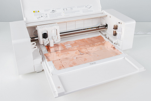
I'm using the Silhouette Curio, a programmable vinyl and paper cutter, to cut through copper tape. It isn't a trivial piece of equipment, and it is costly at $120 (on sale at Michaels). I still haven't wrapped my head around the software either, which is why the current stickers don't look so nice (but they work!). The end-game is to hammer out the 10 or so essential beginner circuits and get those designs to a die-cutting sticker manufacturer.
At first, I was soldering the parts to the copper tape. Without soldering, a tiny dab of jewelry glue and then Bare Conductive paint dabbed over the connection worked great. I'm now experimenting with mixing different glues in with the conductive paint and characterizing the results.
The micro:bit is a great piece of introductory hardware priced just right at $14.95 and packed with tons of attractive features. One of the features I'm most fond of is how agnostic it is toward programming environments. Beginners can choose the block-based/JavaScript IDE MakeCode developed by Microsoft or the MicroPython IDE, while more advanced programmers can use MicroPython or straight C++ on the mbed platform.
The six teachable moments in microcontroller basics have been drilled into me so well by Jeff Branson that I can't escape them --- and they hold to be very effective when teaching. They are:
Input/Output
Analog/Digital
Read/Write
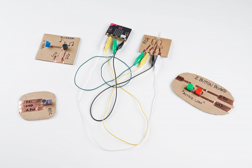
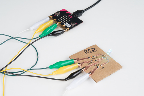
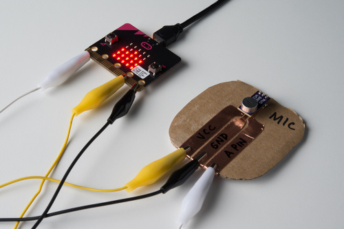
With these six themes, I created the modules. I've organized the pile by type: rounds are inputs, and rectangles are outputs. For the inputs I made an Electret Mic BOB module, a two-button board module, a photocell module, a switch module and a tilt sensor module. For the outputs I made a buzzer module, an RGB LED module, a servo module and a larger speaker module.
I also have this weird thing --- the bigger something is, the easier it is for me to understand it. Troubleshooting a problem on a breadboard usually means ripping up and starting over. With everything connected through alligator clips and visible/large/labeled traces it is much easier.
As I continue to develop around this idea, I want to incorporate ways to up the difficulty. Currently these are single layer, but with the addition of paper or more cardboard and possibly the use of coiled paper clips to use as vias, the concept of multilayered PCB design can be explored. I'm also looking into creating a "library" of through-hole and SMD parts for the Curio machine. I want to get an ATmega 328 DIP in some cardboard and see what I can come up with.
The goal is to not abstract the circuit design as part of the process of learning microcontroller basics and to take a more holistic approach (cost and accessibility included) to learning about circuits and programming.
