Swarm x SparkFun
Today's guest post will focus on the capabilities of Swarm, and Swarm’s network architecture in conjunction with SparkFun.
This is a guest blog post from Rohan Verma and our friends at Swarm Technologies. Swarm provides the world’s lowest cost, global connectivity for Internet of Things devices. All of this in orbit at 450-550km altitude, providing fully global coverage.
Intro
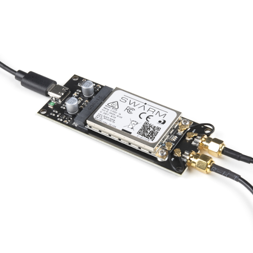
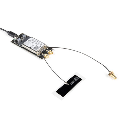
We’re excited to introduce one of the newest additions to SparkFun’s product line, the Satellite Transceiver Breakout - Swarm M138! At the heart of this breakout board is the Swarm M138 Modem which is a Mini-PCI Express (mPCIe) form factor board consisting of a satellite transceiver and a GNSS receiver. This blog post focuses on the capabilities of Swarm, and Swarm’s network architecture.
The Satellite Transceiver Breakout - Swarm M138 enables any user to access the full functionality of the Swarm network via the Swarm M138 Modem. The board design includes a USB-C interface for power and/or serial data, in addition to a full set of breakout pins which give the user access to features such as the GPIO pin available on the Modem. The on-board power circuitry makes it easy to supply the M138 Modem with the power that it needs to transmit message packets to space.
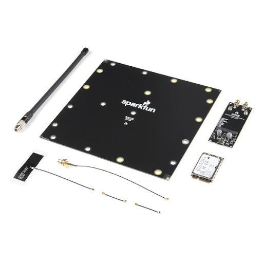
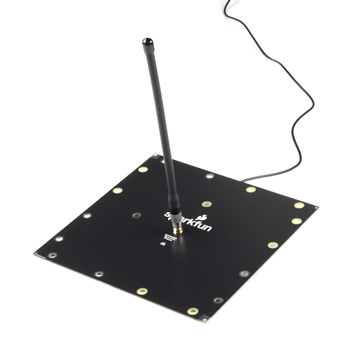
The kit includes everything needed to start transmitting on the Swarm network (including a ground plane, which is required for the VHF antenna). The breakout pins make it easy to hook up the board to a microcontroller, such as an Arduino Pro Mini, to monitor sensors and transmit data from anywhere in the world. The downlink (2-way) functionality makes this Modem great to send configuration information back to the device as well without having to physically access the unit.
What is Swarm?
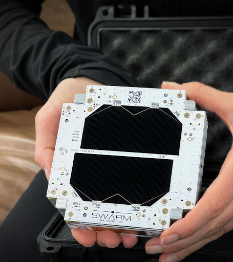
Swarm is a low-cost IoT satellite connectivity provider with one goal; To connect people and devices anywhere, at all times, at the lowest cost. Swarm accomplishes this through the use of sandwich sized satellites named “SpaceBEEs”.
Swarm’s SpaceBEEs communicate with their ground device named the Swarm M138 Modem to transmit and receive small packets of data from anywhere in the world. The Modems can transmit and receive up to 192 bytes of data using a standard data plan of 750 packets/month. Each data plan costs $5/month and is billed annually and there are no other associated fees.
Overview of the Swarm Network
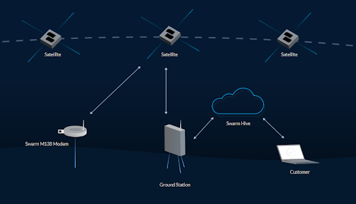
When a SpaceBEE passes over any given location, it will send out beacon packets to Swarm Modems that are in their receiver state. The Modem’s antenna will need to have a clear view of the sky, and a low RF noise environment to receive this satellite beacon.
Format of a satellite beacon packet:
$RT RSSI=,SNR=,FDEV =,TS=,DI=*xx
Once the Modem receives this satellite beacon, it will attempt to transmit any queued transmission packets to the satellite. Message packets that are successfully received by the satellite will then be acknowledged by the satellite back to the Modem. The Modem will then discard the message packet from its outgoing transmission queue.
The Swarm M138 Modem can store a maximum of 1000 outgoing message packets. Each message packet is held for a default duration of 48 hours, which is user configurable, after which the packet will be discarded if not transmitted.
The satellite will then carry that message packet until it passes over a Swarm ground station. The satellite will downlink the message packet to the ground station after which the data will be routed to Swarm’s cloud platform named the Swarm Hive. The user can then view their data on Hive, or extract that data using Swarm’s REST API, or webhooks.
The Swarm Hive will retain data for 30 days before it is discarded, so it is best to pull that data from the Hive to reference it later. Swarm has a Python Script example that you can download by clicking here.
Getting Started
Getting started with the Satellite Transceiver Breakout is a quick and easy process from getting your parts unboxed, to transmitting your first message on the Swarm network.
The first step is to install the Swarm M138 Modem onto the breakout board. To do this, remove the two M2.5 screws from the standoffs on the board. Align the M138 Modem’s mPCIe connection pins with the breakout board’s connector and insert the Modem at an angle into the connector. Once the Modem’s pins are inserted into the connector, gently hold the Modem down over the standoffs and secure it in place using the two M2.5 screws. For best results, do not tighten one screw fully before inserting the other screw into its respective standoff.
Connect the GNSS antenna to the u.FL connector labeled “GPS” on the Swarm Modem. Then connect the u.FL to SMA adapter cable to the u.FL connector on the Swarm Modem that is labeled “VHF”.
Secure the SMA connector of the u.FL to SMA adapter cable to the included ground plane using the washer and nut. Screw the Swarm VHF antenna onto the SMA connector while ensuring that it is hand-tight.
For best results, place the VHF antenna and ground plane at least 1m above the ground, or any solid surfaces.
Download and install the SparkFun Python3 PyQt5 GUI from GitHub here to interact with the Swarm Modem. Once installed, use a USB-C cable to connect the board to your computer. The board can be powered using a USB-C port on your computer, or a USB 3 port. Select the appropriate COM port and test the communication interface by pressing the “Configuration Settings (CS)” button. The Modem’s Device ID and Name will be displayed on the serial monitor in the format:
$CS DI=<dev_ID> ,DN=<dev_name>*xx
The next step is to place the device in an outdoor location with a clear view of the sky, away from any sources of RF noise. Once the device is set up outdoors, use the “Receive Test 1Hz (RT 1)” predefined message in the Python3 GUI to measure the background RSSI. The background RSSI measurements will be updated once every second and represent the noise floor in the testing environment. The measured background RSSI value should be between -95 and -105 dBm for reliable communication on the network. A lower, more negative, value is preferred.
The Modem will not be able to reliably communicate with the satellites if the reported background RSSI value is > -93 dBm. Try moving the device to a different testing location to observe how the measured value changes.
After confirming that the background RSSI is within the specified range, the next step is to queue some message packets on the Modem for transmission. The quickest way to queue messages for transmission is to use the predefined messages in the GUI shown at the bottom of the list. The message packets will be queued for transmission for a default hold time of 48 hours after which they will be discarded if not transmitted.
The message packet hold time is user configurable for each transmission command. Please refer to the Swarm M138 Modem’s Product Manual for more information, and for a full description of available commands.
The queued transmission packets will be transmitted when a satellite passes over the device’s location and beacons the Modem. The next satellite pass over your location can be predicted using the Swarm Satellite Pass Checker. There is also a YouTube video available that describes the pass checker’s functionality in more detail available here.
To know if a satellite is attempting to communicate with the Modem, ensure that the “Receive Test 1Hz (RT 1)” command is enabled. Observe the serial monitor for satellite beacons in the format:
$RT RSSI=<rssi_sat>,SNR=<snr>,FDEV=<fdev>,TS=<time>,DI=<sat_id>*xx
The Modem will attempt to transmit queued message packets after receiving the satellite beacons. Each successful transmission will be acknowledged by the satellite and will be displayed on the serial monitor in the format:
$TD SENT RSSI=<rssi_sat>,SNR=<snr>,FDEV=<fdev>,<msg_id>*xx
The transmitted data packet will then be visible on the Swarm Hive shortly after transmission.
What are you building with the Satellite Transceiver Breakout - Swarm M138?
We would love to hear from you if you have been experimenting with the Swarm Network. Email support@swarm.space with a brief description of your project, and any pictures that you have, to be featured on a future blog post!

