Automatic Light Switch on the Internet of Things
The creation of an automatic light switch using infrared tripwires.
Backstory
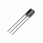
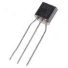
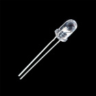
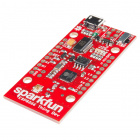
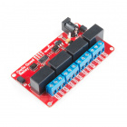
I just moved into my first new home and found the lighting situation in my garden-level office to be absolutely horrendous fluorescent tubes. For the time being I'm using two very large lamps, but I'm bad at remembering to turn them off when I leave, and getting across the room in the dark when I arrive is a dangerous affair. I decided to put my things on the Internet of Things by designing an automatic light switch using the SparkFun ESP8266 Thing Dev, SparkFun Quad Relay, and an infrared LED/receiver pair as a tripwire to turn the lights on and off. You can find all the parts I used for this project below.
SparkFun Qwiic Quad Relay
COM-15102Infrared
The largest hurdle to this project was creating a 38kHz infrared signal that would act as an invisible tripwire to activate the lamps. The next hurdle was creating a second tripwire to act in conjunction with the first to accurately track people entering and exiting the room. Before we dive into the coding aspect of this project, first you must understand a smidge about infrared. Infrared is EVERYWHERE! Just outside of the visible spectrum, infrared is given off by our body in the form of heat, the sun blasts IR from space all the time and, not to be outdone, other stars share their IR with us as well. Because of this, the infrared tripwire must be modulated to be recognized by the IR receiver.
To create this signal I wanted to start from the ground up to get a better understanding of microcontroller timings. Generating a 38kHz signal from a SparkFun ESP8266 Thing operating at 32MHz will require some delays, but for how long? What will be the duty cycle of this signal, if any? To start I did some simple math:
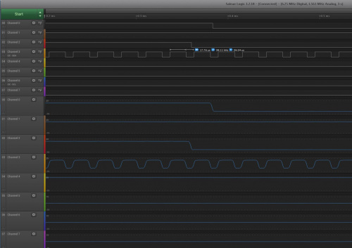
Logic Analyzer
Alright that's good enough for a starting point. If I did not have a logic analyzer at this point then I wouldn't be able to fine tune the signal to discover some other unknown time hang ups. I took the final result and wrote the IR LED high for half the calculated delay time using the delayMicroseconds() function (13us) and low for the other half
(another 13us). Analyzing the signal showed that the signal was too slow, but why? After some investigation I found that writing the pin high takes some time to complete, which is not really something I've had to take into consideration before. I mean of course it does, but this is exactly the kind of stuff that is so great to come across when doing a project, because this is how I learn something new.
The time to write a pin high on an ESP8266 is approximately ~1.5us. Reducing the delay to about 23us gave just enough delay to generate a 37.89MHz wave which is enough for my purposes. Implementing the signal wasn't as successful. Looking at the datasheet for the IR receiver I discovered that blasting it with a IR signal continuously only forces the receiver to turn off signal capture for a time.
I searched our website for some help and came across Nate's tutorial on rebuilding the Lumitune, which really brought the whole thing together. If you look at the tutorial, he provides code for this large project that revolves around blocking an IR signal to play a piano key. In his code he simply pulsed the IR LED for a short burst and immediately read thereafter to see if it had been read. He delays for one millisecond between these bursts to keep from overloading the IR receiver. Of course! Sometimes you go down the rabbit hole and have a hard time getting perspective on your project. This is exactly what I needed to find. I set up the first and second IR transmitter/receiver pair and had two working tripwires. I futzed with the duty cycle to see how it affected the receiver, but found that 50 percent was sufficient.
The Code
To have this work correctly I mentioned that my goal was to have two IR tripwires working together to determine whether a person was entering the room. With two I can determine whether a person is coming or going from the room, because it informs me of the direction they're walking.
Direction is vital because I can keep track of the number of people entering or exiting a room. By keeping track of the number of people in the room, I can prevent the lights from turning off whenever any one person departs the room and instead only when the room is empty. That's an important distinction and a common use case for my automatic light switch. Of course this is not a perfect system; I can imagine an instance where two separate people, one leaving and one entering, trigger both IR tripwires simultaneously. I can imagine a line of Redcoats walking down my hallway shoulder to shoulder, and my setup only senses one person when there are actually three in a line.
For all the edge use cases I'm simply going to put a button near the entrance to turn off the lights, and because we're on the internet, I'll be able to turn the lights on and off with my phone as well. To implement this well, I want the second IR tripwire to trigger after the first in a specific window of time so that I can accurately determine direction. Is there something else I should be considering? Let me know below.
The code for setting up two SparkFun EP8266's was not difficult. Our hookup guide shows how to set up a simple server and the client example code provided by Espresif was all I needed to get communication between the two working. Looking toward, the future I want the web page to have a better indicator for the lights. If you're interested in the code for your own project or are feeling curious, I've linked all the code below.
Infrared Circuit
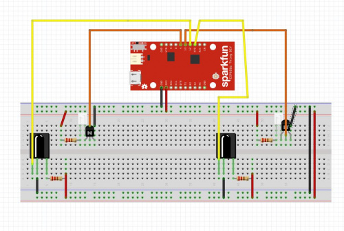
Belolw is the circuit for the infrared tripwires. One thing to note is that the IR LED can use up to 50mA of current, which is more than the pin on the ESP8266 can provide. I use a NPN transistors with 68 Ohm resistors to provide the proper current. I actually breadboarded the circuit on two seperate breadboards so I could separate them as much as possible. However, the IR LEDs still managed to trigger the wrong receivers so I used aluminum foil to create a cone around each LED.
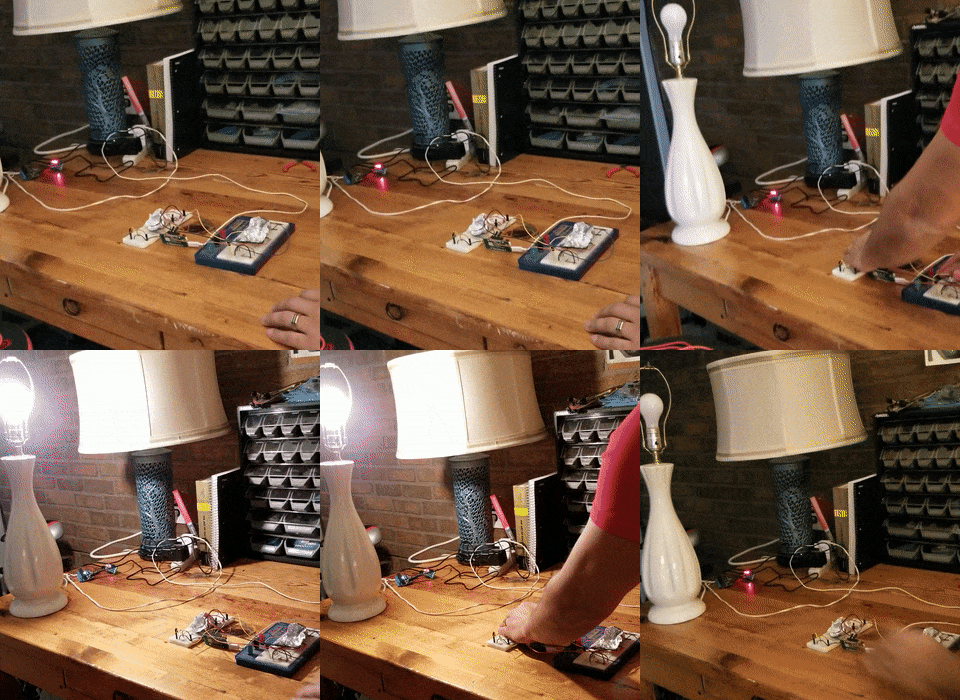
The ESP8266 controlling the SparkFun Qwiic Quad Relay was hooked up to the I2C pins. Check out the hookup guide for the Quad Relay if you want to know more. That's all, folks! In the GIF below I show a single lamp being turned with the specific order using the "direction" logic talked about in the code above, followed by the lights turning off by going in the opposite "direction."
The Physical Housing
The design for the physical housing of the project will have to occur sometime after this post. As of right now it's just a hodge podge of wires. My plan is to place the IR LED and receiver pairs some distance apart in the hallway. I'll probably laser cut small boxes to house the hardware with a small hole to direct the LED and alternatively, a small hole to house the receiver.
Looking to the future
As I was working on the write up for this project it occurred to me that if two people were walking close together that the logic of the code would not work. The first tripwire will be off until the first person either triggers the second or the window of time to trip the second ends. If two people are close together then a person could slip in without being sensed! I think instead it would be smarter to create a "stack" of entrances and exits, where each tripped tripwire has an associated time stamp. I can then compare tripped tripwires and their timestamps and make decisions based on the time between them. Let me know if you guys have any suggestions in the comments below!


