Neato Robotics XV-11 Tear-down
We tore apart a Neato Robotics XV-11 robotic vacuum cleaner and did a little reverse engineering.
On the surface, the Neato Robotics XV-11 vacuum cleaner seems like just another Roomba with a square front, but it caught our attention because of the cheap and innovative Lidar device it uses to sense the room it's cleaning. It claims to "map" the room it is in and detect doorways so that it can clean a whole room before exiting. So we went ahead and ordered one to tear-down and hack. Then on November 15th, RobotBox announced a $200 prize for the first person to post usable Lidar code. At the time of this writing, the purse is up to $800. While we don't have a usable hack (yet, muahahaha), we did a thorough tear-down and sniffed around the Lidar signals for all you hackers that don't want to drop $400 on a vacuum.
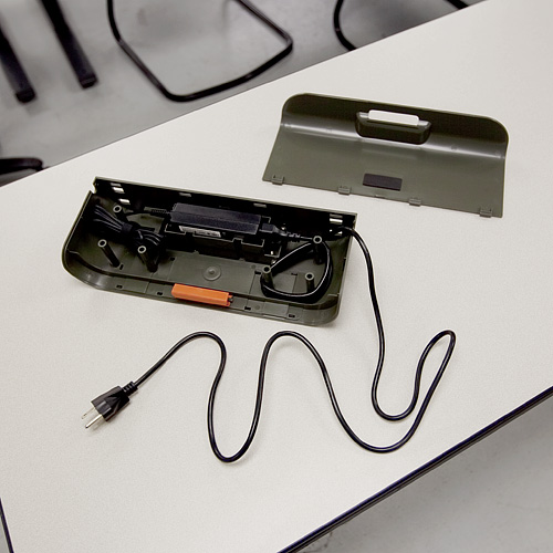
On first start up, the bot made some cutesy beep-boop robot noises and insisted that we charge its battery (the robot always refers to itself in the first person on its LCD display). So we stuck it on its wall-charging station for a while. Nothing fancy here, just a couple of spring-loaded contacts that press on the contacts on the back of the bot. However, Neato made the base charger as a simple structure for a standard power supply so the user can remove the power supply and plug it in if desired.
Once the bot was charged, we gave it a test run. The XV-11 came with a flexible magnetic strip that allows the user to "block" the bot from areas of a room, so we had a little fun laying down the strip to box the bot in. It successfully vacuumed one side of an office before we purposely confused it with the magnetic strip. When we gave it the command to return to the base station, it seemed pretty lost, and just ran into a wall and powered down a couple of feet from the charging station.
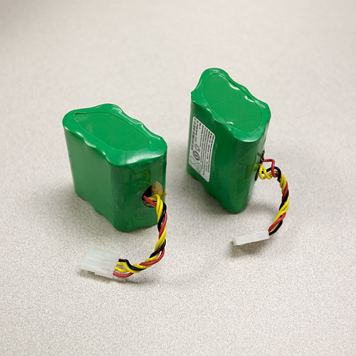
For the tear-down, we first removed the batteries from the bot. They are a couple of standard 7.2V 3200mAh Nickel Metal-Hydride cells.
After removing a couple more panels, we got down to some guts.
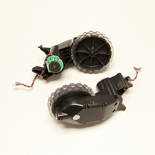
There's a suction fan, two spring-loaded wheel assemblies, and the vacuum brush. The wheel assemblies are one-piece motor-with-gearbox combinations. Each motor has a (seemingly custom) digital encoder. The axles are spring loaded and trigger a simple tactile switch to detect if the robot has been picked up (or fallen off a cliff).
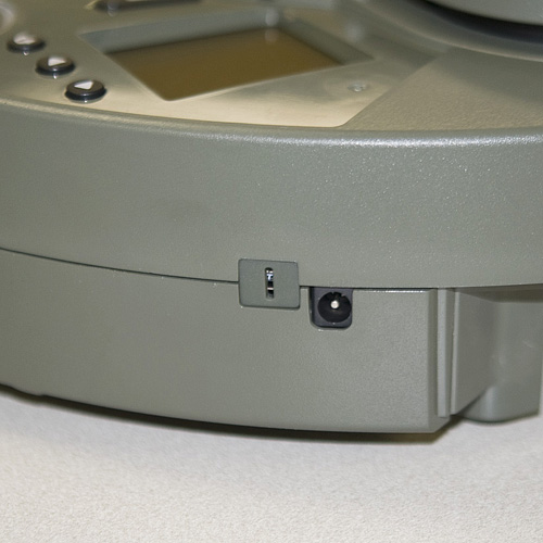
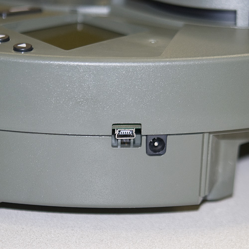
Before removing the rest of the case, we poked around a bit more and discovered this:
A "hidden" USB port. It's possibly for USB bootloading or troubleshooting at the factory. We also spotted the single wall sensor on the right side of the bot.
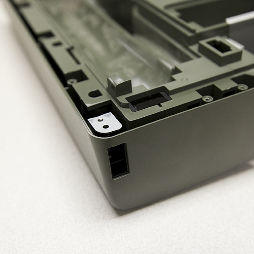
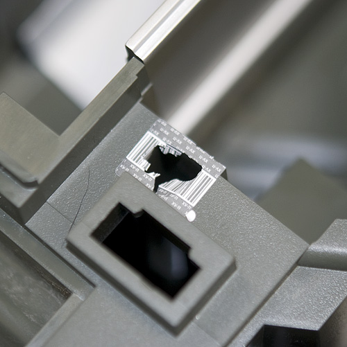
The last two screws to remove the top half of the case were hidden under some flimsy bar-coded warranty stickers. So we promptly voided the warranty.
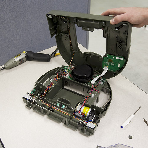
Now we have full access to all the guts of the XV-11.
You can see the Lidar assembly sitting on top of the main processor board, the drive motor for the brush, and the daughterboard for the LCD and buttons. In the front of the bot, we can also see the optical switches for cliff detection, as well as the magnetic sensors that detect the magnetic strip. The Lidar device sits on top of the mainboard, which is controlled by a beefy AT91SAM9XE. Since the Lidar is what we're most interested in, we pulled it off first.
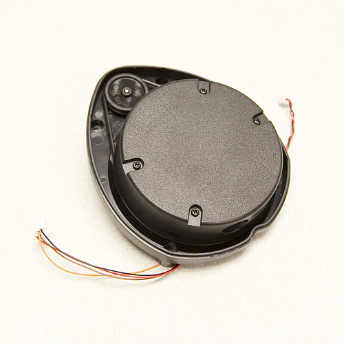
The Lidar unit is fully enclosed in a plastic "turret". It has two wires coming off of the motor that spins the turret, and four wires coming from the inner assembly. We removed the top of the turret to get a look at the mechanism.
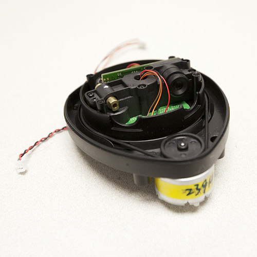
Inside you can see the laser and the CMOS imager that the Lidar uses to detect distance to objects. The white paper on this device insists that it can be built for less than $30, but right now the laser can only be bought if it's inside the robot. Still $400 dollars is a low price for a device that does 1-degree accuracy planar scanning at 10Hz. There are four wires running to the laser assembly. Upon closer inspection, we see that these wires are soldered to pads on the board labeled "TX", "RX", "GND", and "VCC". So it's not exactly tough to figure out what communication protocol the device uses.
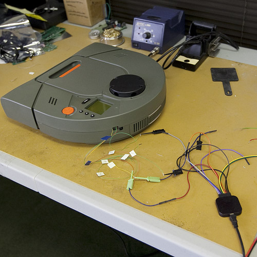
In order to start getting data from the Lidar, we soldered some leads to the communication lines and the motor lines, and assembled the bot again. We fed the lines out of the hole for the USB port on the case of the bot, so the bot should now be able to run normally while we sniff the data lines. The motor spinning the Lidar runs using a 12V square wave with a 25% duty cycle. The logic for the Lidar is at 3.3V, so we hooked up one of our logic analyzers and let the bot run.
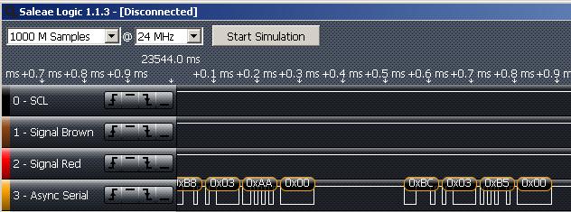
Here's a snippet of the data that we pulled off of the Lidar while the bot was in normal operation.
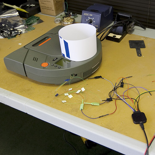
Sure enough, the TX line is spitting out data at 115200 baud. Right now, we don't know what the data means, so we conducted two more similar tests. In the first we placed a 13cm round paper "shield" around the rangefinder, so that when it runs, it should see the same distance at all 360 degrees.
Sure enough, the bot ran for about 10 seconds, then stopped and displayed "LDS error. Visit website." We did the same test with a 22cm shield, and the same thing happened. In the logic analyzer for both tests, the Lidar spit out the same value the whole time, but different values depending on whether we were using the 13 or 22cm shield. If you are interested, here are the analyzer files for the three tests. The software for the analyzer is free online.
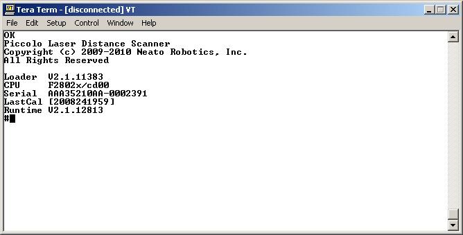
For our last test, we pulled the Lidar out of the bot again. This time we hooked the data lines straight into TeraTerm, reset the power to the device, and saw this
When we spin the turret by hand, the device prints the message "Spin..." and then starts spitting out data (unreadable by TeraTerm of course). We haven't got it hacked yet, but it's a good start. Hopefully some interested party can use some of this data to get some usable software going. In the meantime we're going to keep digging up data. Happy hacking!
