When 12 Volts Fights Back
Protecting a Teensy from Automotive LED Strip Faults
What started as a TRON-inspired motorcycle lighting project turned into a useful lesson about signal integrity, fault protection, and the realities of connecting microcontrollers to automotive electrical systems.
Paul's Deep Dives
Hello SparkFans! Paul here from PJRC. I spend a lot of time on the PJRC forum helping people solve all kinds of tricky problems. Some of those threads turn into deeper dives on how things really work.
In Paul’s Deep Dives, we'll revisit some of my favorite forum discussions. Along the way, we fill in the gaps, add context, and connect the dots so you not only see what worked — but understand why it worked. Enjoy!
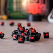
The project itself was ambitious: a TRON-inspired motorcycle lighting system built around a Teensy 4.1 and several WS2815 LED strips powered from the motorcycle's 12V electrical system. On the surface, the design seemed straightforward enough - the LEDs were powered directly from the bike, the Teensy was powered separately through USB, and the only connection between them was the data signal.
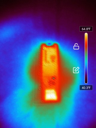
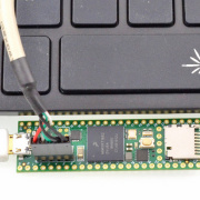
Then two Teensy boards died...
The symptom was dramatic. As soon as the controller was connected to the installed LED system, the board began heating rapidly. The exact cause wasn't immediately clear, but it raised an important question: how do you protect a 3.3V microcontroller from faults that originate in a 12V system?
As the discussion unfolded, we ended up exploring several topics that come up frequently in embedded systems design: level shifting, fault protection, isolation, and the difference between something that works on a bench and something that survives in the real world.
Why Separate Power Supplies Don't Guarantee Isolation
One of the first assumptions many people make is that separate power supplies automatically mean electrical isolation.
Unfortunately, that's not true.
Even if a microcontroller has its own power source, a signal wire can still become a path for fault current. If a data line is accidentally connected to 12V, develops an internal short, or encounters some unexpected failure inside another device, that current can flow directly into a microcontroller pin.
Modern chips include ESD protection structures that help survive brief static events, but they're not designed to absorb sustained fault current. Once those structures are overwhelmed, damage can spread quickly.
So, the practical question I wanted to address was simple:
How do we keep a 12V fault from destroying a 3.3V microcontroller pin?
A Simple Protection Circuit
The first approach I suggested was a two-stage protection circuit using resistors and a zener diode.
Rather than connecting the signal directly to the Teensy pin, the signal passes through resistors while a zener diode clamps excessive voltage before it can reach the processor.
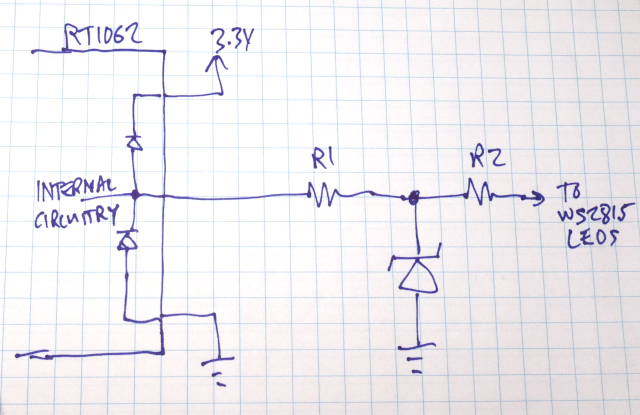
The idea is straightforward. The resistor limits current. The zener limits voltage.
Neither component is particularly effective by itself, but together they can transform a potentially destructive fault into something the hardware can survive.
Why I Didn't Recommend a Regular Diode
One of the questions that came up was whether a normal diode could replace the zener diode. The short answer is no.
A regular diode conducts in one direction and blocks in the other. Under a positive 12V fault condition, it wouldn't do anything useful.
A zener diode is different because it's specifically designed to conduct in reverse once a certain voltage threshold is reached. Under normal operating conditions it does essentially nothing. When the voltage rises beyond its intended range, it begins conducting and diverts current away from the protected circuit.
That's exactly the behavior we want.
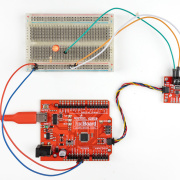
Theory Is Nice. Testing Is Better.
Rather than speculate endlessly about component values, I put together a quick breadboard test using parts from my bin.
The first thing I discovered was that a 3.3V zener diode—what many people would naturally choose—didn't work very well in practice.
Although the diode was rated at 3.3V, it began conducting early enough that it pulled the Teensy's output signal down to about 2 volts. That's an important reminder that zener diodes don't switch instantly from OFF to ON. They transition gradually through what's often called the zener knee, and the actual behavior depends heavily on current and operating conditions.
Switching to a higher-voltage zener produced much better results.
At that point I disconnected the Teensy, applied 12V to the protected side of the circuit, and measured the voltages throughout the network. The zener clamped the fault voltage, the resistors limited the current, and the voltage reaching the Teensy side stayed within a range that appeared survivable.
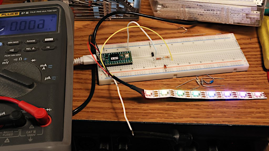
Then I reconnected the Teensy and repeated the test. The board survived and continued running normally.
That doesn't mean the circuit is indestructible. It simply means the fault current was reduced enough that the hardware could tolerate it.
And in protection design, that's often the goal.
Protection Versus Signal Integrity
The next challenge appeared almost immediately.
The protection circuit worked but the LEDs didn't.
When I tested the circuit with actual WS2815 LEDs, the data signal became unreliable. The protection components that helped keep the Teensy safe were also affecting the high-speed signaling needed by the LED strips.
This is one of the most common tradeoffs in electronics design. The same resistor that limits fault current also limits signal drive strength. The same diode that protects against overvoltage can add capacitance that distorts fast edges.
In other words, every protection mechanism comes with a cost.
Increasing resistor values improves protection but weakens the signal. Reducing resistor values improves signal integrity but allows more fault current to flow during a failure. There is rarely a perfect answer. Instead, the design process becomes a balancing act between robustness and performance.
The Level Shifter Question
Throughout the discussion, another issue kept resurfacing: flickering LEDs and occasional color corruption.
Many WS2815 installations behave more reliably when driven from a full 5V logic signal rather than directly from a 3.3V microcontroller output. That's why level shifters such as the 74HCT245 are frequently recommended.
However, it's important to understand that a level shifter solves a different problem than a protection circuit.
A level shifter:
- Improves signal voltage margins
- Helps maintain reliable communication
- Reduces flickering and data corruption
What it does not automatically do is protect the controller from a 12V fault.
In fact, if a fault occurs, the level shifter itself may become the component that fails. Without additional protection, there's no guarantee that a damaged buffer chip won't pass dangerous voltages elsewhere in the system.
My recommendation was to combine level shifting with Schottky diodes, resistors, and supply-side protection rather than relying on the buffer chip to act as a sacrificial component.
When Isolation Becomes the Better Answer
As the conversation evolved, another possibility emerged.
What if the goal wasn't simply protection?
What if the goal was complete isolation?
In that case, resistor-and-diode protection circuits only go so far.
True isolation requires isolators.
Several high-speed digital isolators were discussed, including devices such as the ISO6420 and CMT8020N0. Unlike traditional optocouplers, these parts are fast enough to handle the roughly 800kHz signaling used by WS2812 and WS2815 LEDs.
When powered correctly on both sides of the isolation barrier, these devices can prevent faults on the LED side from reaching the controller entirely.
Of course, isolation comes with its own tradeoffs.
It requires additional components, separate power domains, careful design, and additional cost. But in electrically noisy environments such as motorcycles, vehicles, industrial systems, and large LED installations, isolation can be one of the most effective solutions available.
A Broader Lesson About Troubleshooting
One of the more interesting aspects of this discussion had nothing to do with zener diodes or level shifters.
It was about troubleshooting itself.
As often happens on technical forums, many of the questions centered around gathering more information:
- How is everything connected?
- What powers what?
- Where are the grounds connected?
- Can we see a schematic?
Projects often begin with a design that feels simple enough that documentation doesn't seem necessary.
I've certainly been guilty of that myself.
But once a problem becomes difficult to reproduce or diagnose, documentation becomes incredibly valuable. The process of drawing a schematic frequently reveals assumptions, overlooked connections, and design decisions that seemed obvious during construction but become much harder to track down later.
What I Took Away From This Discussion
By the end of the conversation, it was clear there wasn't a single magic component that would solve every problem.
Instead, the solution was a layered approach:
- Use a proper level shifter for reliable WS2815 communication.
- Add series resistors on data lines.
- Add Schottky diodes to divert fault current away from vulnerable devices.
- Consider zener protection on supply rails.
- Use digital isolation when true electrical separation is required.
- Prototype and test fault conditions before committing hardware.
The biggest takeaway for me is one I see repeated often in embedded systems:
Don't assume a signal wire is harmless simply because the power supplies are separate.
In mixed-voltage systems—especially automotive ones—a signal line can become the path that lets the smoke out.
Footnote
This article is based on the PJRC forum thread "Pretty sure I let out the smoke" and the discussion that followed between forum members while troubleshooting repeated Teensy failures in a motorcycle lighting project.
Original discussion: https://forum.pjrc.com/index.php?threads/pretty-sure-i-let-out-the-smoke.77405/
