The Analog Side of Ethernet: MAC Addresses, PHYs, and Passive PoE on Teensy 4.1
Moving an embedded project from Wi-Fi to hardwired Ethernet can feel like a straightforward upgrade. Plug in a cable, configure an IP address, and enjoy a reliable physical connection. But Ethernet has a **very real** analog side.

Paul's Deep Dives
Hello SparkFans! Paul here from PJRC. I spend a lot of time on the PJRC forum helping people solve all kinds of tricky problems. Some of those discussions offer especially useful insights into how things really work.
Paul’s Deep Dives are written by SparkFun, drawing from Paul’s original forum posts and technical guidance. Each article revisits a discussion from the PJRC forum, adding context and organizing the material into a deeper technical walkthrough while preserving Paul’s original engineering insights.
On the Teensy 4.1, that analog world includes the TI DP83825 Ethernet PHY, transformer isolation, controlled-impedance differential pairs, transient protection, and potentially tens of volts of Power over Ethernet riding on the same cable as the data.
Two discussions on the PJRC forum illustrate both sides of this particularly well. One started with a seemingly simple question: where does a Teensy 4.1's unique MAC address actually come from? The other started considerably more dramatically, with Ethernet PHY chips being destroyed when passive PoE cables were hot-plugged.
Together, they provide a useful look at what is actually happening underneath an Ethernet connection.
The PHY Isn't the MAC
A useful place to begin is with two terms that are sometimes treated as though they describe the same piece of hardware: MAC and PHY.
They don't.
The Ethernet MAC, or Media Access Control layer, deals with Ethernet frames, addresses, and the digital side of moving data. The PHY, or physical-layer transceiver, converts that digital interface into the analog electrical signaling that travels over the Ethernet cable.
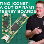
On the Teensy 4.1, the processor is an NXP i.MX RT1062, while the Ethernet PHY is a Texas Instruments DP83825I.
The DP83825I is a 10/100 Mbps Ethernet PHY supporting 10BASE-Te and 100BASE-TX. It communicates with the processor using RMII and handles the electrical interface toward the Ethernet magnetics and cable. TI specifies integrated MDI and MAC termination, a single 3.3 V supply, cable diagnostics, and support for cable lengths up to 150 meters. See the Texas Instruments DP83825I documentation for more information.
That division of responsibility becomes especially important when looking for the board's MAC address.
Where Teensy's MAC Address Actually Lives
Every Teensy 4.1 is assigned a unique MAC address by PJRC, but that address isn't stored in the DP83825 PHY. It is programmed into the non-volatile fuse memory of the i.MX RT1062 processor during PJRC's production testing.
The upper 24 bits belong to PJRC's IEEE-assigned Organizationally Unique Identifier, or OUI, while the remaining bits distinguish individual devices (not to be confused with the popular yogurt brand, which of course is also just the French word for "yes").
This has an important consequence: the identity belongs to the Teensy, not to the PHY chip.
Replacing a damaged DP83825 doesn't replace the MAC address. Likewise, a Teensy 4.1 manufactured without an Ethernet PHY can still contain its PJRC-programmed MAC address.
The same principle extends to Teensy 4.0. Paul Stoffregen clarified in the forum discussion that Teensy 4.0 boards also receive unique MAC addresses even though the Teensy 4.0 does not expose the processor pins needed to connect the native Ethernet interface to a conventional PHY.
For custom boards built around PJRC's Teensy 4 bootloader chip, PJRC similarly provides a unique MAC address using its OUI, with the bootloader programming that information into the processor's fuse memory on first use.
This is different from buying a bare i.MX RT1062 directly from NXP. According to Paul, those MAC fuse locations arrive unprogrammed; the unique Ethernet identity is part of PJRC's provisioning process rather than something inherent to every RT1062.
NXP documents the i.MX RT1060 family's on-chip OTP fuse system in the i.MX RT1060 processor documentation.
Reading the MAC Address
For a Teensy 4.1 using QNEthernet, applications can normally retrieve the address without worrying about the underlying fuse registers:
#include <QNEthernet.h>

using namespace qindesign::network;

uint8_t mac[6];

void setup() {
  Serial.begin(115200);

  Ethernet.macAddress(mac);

  Serial.printf(
    "MAC = %02X:%02X:%02X:%02X:%02X:%02X\r\n",
    mac[0], mac[1], mac[2],
    mac[3], mac[4], mac[5]
  );
}

void loop() {
}
One subtle point is worth emphasizing:
Ethernet.macAddress(mac);retrieves the Teensy's address. It isn't generating or assigning a new one.
The forum discussion uncovered an interesting Teensy 4.0 corner case as well. An early test using QNEthernet returned zeros, even though directly reading the i.MX RT1062 fuse registers produced the expected PJRC MAC address.
The reason turned out to be software rather than hardware. QNEthernet's default "unsupported" driver for a platform without native Ethernet connectivity wasn't fetching the address. QNEthernet developer Shawn Silverman subsequently fixed that behavior.
The lower-level version demonstrates where the information ultimately comes from:
void enet_get_mac(uint8_t *mac) {
  if (mac == nullptr) {
    return;
  }

  uint32_t m1 = HW_OCOTP_MAC1;
  uint32_t m2 = HW_OCOTP_MAC0;

  mac[0] = m1 >> 8;
  mac[1] = m1 >> 0;
  mac[2] = m2 >> 24;
  mac[3] = m2 >> 16;
  mac[4] = m2 >> 8;
  mac[5] = m2 >> 0;
}
Here the MAC address is reconstructed from the processor's HW_OCOTP_MAC1 and HW_OCOTP_MAC0 fuse registers.
This distinction can be useful for designs that don't use the Teensy 4.1's conventional Ethernet hardware at all. A project using an external SPI Ethernet controller, for example, can still use the unique identifier PJRC provisioned into the processor.
And that's where the software side of this story ends.
The other forum discussion dealt with what happens much farther down the stack, where Ethernet becomes analog electronics.
Part Deux: When an Ethernet Cable Carries...54 Volts!?
Power over Ethernet allows data and DC power to share Ethernet cabling. Standards-based PoE systems include mechanisms for detecting and negotiating with a powered device before full operating power is applied.
Passive PoE is different.
A passive injector can simply place DC voltage onto the cable without the normal IEEE PoE detection and classification process. In the forum experiment, the system used a passive injector with a 54 V supply.
That distinction became critical when the powered Ethernet cable was hot-plugged.
The Ethernet magnetics provide galvanic isolation between the cable and PHY, which might make it seem as though a large DC voltage on the cable could never reach the PHY.
Steady-state DC isn't the whole problem.
During connection and disconnection, the cable, magnetics, capacitance, and load form a dynamic circuit. The contacts inside an RJ45 connector don't necessarily make or break simultaneously. For a brief period, the system can become electrically unbalanced.
That transient event can couple a surprisingly large voltage through the magnetics and into the PHY-side circuitry.
Microchip describes this phenomenon in its AN2157 application note on transient protection for PoE systems. The note discusses connection transients and protection circuitry intended to prevent those voltages from reaching PHY communication pins.
The measurements from the Teensy forum demonstrated just how significant the effect could become.
Now A 70-Volt Surprise!?
Forum member mamdos had designed a custom Teensy 4.1 baseboard incorporating passive PoE. After PHY failures, the Teensy was removed and the Ethernet data lines were measured directly while repeatedly hot-plugging the powered connection.
Tests were performed with both six-inch and 100-foot CAT5 cables. Without additional transient suppression, the measured spikes on the PHY side reached approximately 70 volts. That's an enormous excursion for circuitry intended to operate around a few volts.
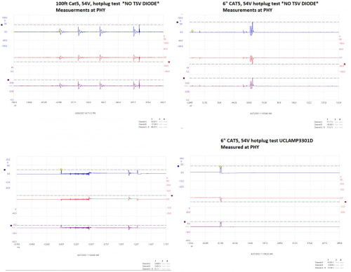
For comparison, TI's DP83825I datasheet specifies an absolute maximum of -0.3 V to 4 V on its MDI pins and warns that stresses beyond the absolute maximum ratings can cause permanent damage. See the DP83825I datasheet for the complete specifications.
This also explains why the failure could appear surprisingly localized. In the reported cases, replacing the DP83825I restored the affected Teensy boards. The processor itself wasn't necessarily the component taking the hit. The PHY was standing directly at the edge of the analog Ethernet interface.
First Attempt: Add a TVS Diode
A natural protection mechanism is a Transient Voltage Suppression diode, or TVS. A TVS behaves somewhat like a very fast voltage clamp. Under normal conditions it largely stays out of the circuit. When the voltage rises sufficiently, it conducts heavily to suppress the transient. The forum experiments initially used a UCLAMP3301D device. The result was dramatic. The roughly 70 V transient fell to approximately 9 V. That's a huge improvement—but it wasn't enough. Another PHY was damaged during hot-plug testing with a load attached. This is an important practical lesson in transient protection: adding a TVS diode doesn't automatically mean the protected node will remain at the diode's nominal working voltage. A real TVS has dynamic resistance, and its clamping voltage depends on the transient current flowing through it. The protection network has to be designed as a system.
Adding Series Resistance
The next experiment added 33 ohm series resistors to each PHY-side Ethernet data line, following the general protection approach discussed in the Microchip application note. With those resistors installed, the measured spike fell further, to around 7 V.
Repeated hot-plug testing no longer immediately destroyed the PHY. But there was still a problem. Seven volts is still outside the DP83825I's absolute maximum MDI rating.
So while the practical result was encouraging, it wasn't evidence that the circuit had become electrically safe and increasing the resistance isn't free.
Protection Versus Signal Integrity
Paul raised the key engineering question in the forum: what do those additional series resistors do to Ethernet performance, particularly with long cables?
Ethernet is a controlled-impedance transmission system. The twisted pair has a nominal differential impedance of about 100 ohms, and the PHY and termination network are designed around that environment.
Adding substantial series resistance changes the impedance presented to the cable. That's why a resistor that looks attractive from a transient-protection perspective may be less attractive from a signal-integrity perspective.
The forum discussion therefore moved toward a more nuanced design question: Can a lower-resistance series element be combined with a better TVS device to achieve sufficient clamping without significantly disturbing the Ethernet interface?
One participant worked through the equations using TI's ESDS312 protection device and arrived at approximately 13 ohms for the protection network being considered, considerably less than 33 ohms. Other contributors pointed toward TI's own Ethernet protection reference designs, which use carefully selected ESD protection and termination components rather than simply placing large resistors in series with every signal. That is a better way to think about the problem. The TVS diode and series impedance aren't independent components. Together they determine how much transient current flows and what voltage ultimately appears at the PHY.
Why Active PoE Is Different
It's also important not to turn this particular failure mode into a warning against PoE in general. The forum testing involved passive PoE.
Standards-based IEEE PoE systems perform detection and classification before normal operating power is supplied. A passive injector that continuously places 48 or 54 V onto the cable doesn't have that same behavior. That makes hot-plugging passive PoE a particularly harsh case.
So a Teensy connected to an ordinary Ethernet network isn't suddenly at risk of seeing a 70 V transient simply because an RJ45 cable was unplugged. Nor should the forum measurements be interpreted as showing that every standards-compliant PoE system produces the same behavior.
The caution is much more specific: If a custom Teensy Ethernet design combines passive PoE with hot-plugging, transient protection deserves serious attention.
Magnetics Are Isolation, Not Magic
Perhaps the most useful lesson from the discussion is that transformer isolation shouldn't be mistaken for immunity from transients. Ethernet magnetics do an excellent job of providing galvanic isolation and rejecting common-mode signals during normal operation. But a rapidly changing, unbalanced condition is different from steady-state DC.
Parasitic capacitance, leakage inductance, cable inductance, load capacitance, switching behavior, and connector sequencing can all matter during a transient. That is why a system can be perfectly well isolated at DC and still experience a damaging voltage spike during a fast connection event. It's also why protection components need to be considered as part of the physical Ethernet design rather than as an afterthought.
What This Means for a Custom Teensy Ethernet Board
For a conventional Teensy 4.1 Ethernet connection, PJRC has already handled most of the difficult digital pieces. The i.MX RT1062 contains the Ethernet MAC, the board carries the DP83825 PHY, and PJRC provisions a globally unique MAC address into the processor.
A custom carrier board, PoE interface, or alternative Ethernet implementation pushes the design farther into analog territory.
At that point, it's worth thinking about the complete signal path: cable -> connector -> magnetics -> transient protection -> PHY -> RMII -> processor
Power added to that same cable creates another path that has to coexist safely with the first one. And that's where the two forum discussions ultimately connect. A MAC address may look like a software property, but on Teensy it's permanently provisioned into silicon.
An Ethernet cable may look like a digital connection, but the last few centimeters between the connector and PHY are very much an analog circuit. Hardwired networking isn't just Wi-Fi with a cable attached. It is a high-speed differential interface connected to potentially 100 meters of transmission line—and, with PoE, potentially dozens of volts as well.
Understanding that physical layer is what separates an Ethernet connection that works on the bench from one designed to survive the real world.
Further Reading
The Texas Instruments DP83825I product page and datasheet provide the electrical specifications and absolute maximum ratings for the PHY used by Teensy 4.1.
Microchip's AN2157: Transient Protection in Power Over Ethernet Applications explains how PoE connection transients develop and discusses protection techniques.
NXP's i.MX RT1060 documentation includes the processor documentation covering the RT1062 and its on-chip OTP/fuse system.
Some Products to Consider
$31.50
Footnote:
This article is based on two PJRC forum discussions: Don't blow your Teensy 4.1 ethernet PHY when using passive PoE and Does the PHY chip on the T4.1 have a unique MAC address?, and the technical discussion that followed between Paul Stoffregen and other PJRC forum members.