Unleashing FlexIO: Building the Interfaces Teensy 4 Wasn't Born With
Need SPI? Use SPI. Need I2C? Use Wire. Need a UART? Pick a serial port and get on with the rest of the project.
Most of the time, talking to a peripheral from a microcontroller is pleasantly...basic.

Paul's Deep Dives
Hello SparkFans! Paul here from PJRC. I spend a lot of time on the PJRC forum helping people solve all kinds of tricky problems. Some of those threads turn into deeper dives on how things really work.
In Paul’s Deep Dives, we'll revisit some of my favorite forum discussions. Along the way, we fill in the gaps, add context, and connect the dots so you not only see what worked — but understand why it worked. Enjoy!
But every so often, the interface on the other end doesn't fit neatly into one of those boxes. Maybe it's a 16-bit parallel LCD. Maybe it's a camera producing a dozen bits every pixel clock. Maybe it's an ADC with several data lines shifting simultaneously. Or maybe the interface is technically SPI, but the electrical path introduces enough delay that sampling MISO at 50 MHz becomes the real problem.
That's when the NXP i.MX RT1062 inside Teensy 4.x starts to get interesting.
Buried among its more familiar peripherals is FlexIO: a collection of configurable shifters, timers, logic, and pin routing that can be assembled into interfaces the chip doesn't otherwise provide. PJRC describes it as a sort of “build-your-own ports” peripheral, capable of implementing UART, I2C, SPI, I2S, PWM, and more specialized interfaces.
A long-running discussion in the Teensy community explored just how far that “and more” can go. What began as an idea for a general-purpose parallel library turned into experiments with LCDs, cameras, ADCs, classic processor buses, DMA, external clocks, and even synchronizing all three FlexIO peripherals.
Along the way, another discussion raised an equally useful question: when should we use FlexIO at all?
The answer requires going below the Arduino API and looking at what hardware is actually inside the RT1062.

First, Three Very Different Kinds of “SPI”
One of the easiest traps here is terminology. The RT1062 has several peripherals whose names sound similar but which solve very different problems.
LPSPI: The Normal SPI Peripheral
LPSPI is what most of us mean when we say “SPI.” Teensy's normal SPI library uses this hardware.
On Teensy 4.1, three SPI ports are exposed, and for ordinary sensors, displays, converters, and other SPI devices, this is almost certainly where you should start.
FlexSPI: High-Speed Memory Interface
FlexSPI is something different.
It's primarily designed for high-speed memory devices. Teensy uses one FlexSPI interface for its program flash, while FlexSPI2 connects to the memory expansion pads on the bottom of Teensy 4.1.
FlexSPI has some sophisticated timing capabilities, including DQS, or data-strobe support. But programming FlexSPI for an unusual device means getting into its low-level command machinery and lookup-table, or LUT, instructions.
FlexIO: A Peripheral Construction Kit
Then there's FlexIO.
Instead of giving us a complete SPI controller, FlexIO gives us lower-level building blocks. Each FlexIO peripheral provides shifters and timers plus logic for routing and controlling signals. The FlexIO_t4 library exposes this hardware on Teensy and already uses it to implement things such as additional serial and SPI ports.
But emulating SPI is a pretty boring use for FlexIO.
The really interesting question is: what happens when we stop trying to recreate peripherals that already exist?

Starting With a Parallel Bus
The community discussion started with a proposal for a general-purpose parallel interface library.
The wish list was ambitious: 4-, 8-, 16-, and potentially wider buses; flexible pin ordering; sustained speeds in the tens of megahertz; an optional hardware-generated clock; non-blocking operation; and support for rearranging bytes, nibbles, and individual bits as data moves through the system.
The obvious application was displays.
Several LCD controllers support 8080-style parallel interfaces, and moving a 16-bit pixel in one bus operation rather than serializing it over SPI can make a substantial difference. But the discussion quickly moved beyond displays.
People suggested high-speed ADCs and DACs. Cameras. Classic 6502-family buses. Multiple ADC data outputs clocked simultaneously. One user wanted to capture 12 parallel bits from an ADC at around 50 MHz.
At that point, we're not really talking about a display library anymore.
We're talking about a programmable digital interface.
Why Not Just Bang the GPIO Registers?
That's a reasonable question, particularly on a 600 MHz Cortex-M7.
Direct GPIO can be extremely fast. Several people in the discussion already had parallel display drivers working this way. One Teensy 3.6 implementation could perform a full-screen blit in roughly 7.7 ms, while another Teensy 4.1 display implementation mentioned in the discussion could update a 320×480 16-bit display in roughly 5 ms.
So raw speed isn't necessarily the reason to use FlexIO.
The bigger advantage is that FlexIO can move the timing-critical part of the protocol into hardware.
Suppose every parallel write requires something conceptually like this:
DATA_PORT = value;

WR_LOW();
delayNanoseconds(...);
WR_HIGH();
That can be fast, but the processor is participating in every transfer.
With FlexIO, the data goes into shifter buffers while a hardware timer generates the clock or write pulses. Once configured, the shifter and timer advance the interface without requiring the Cortex-M7 to manually toggle the signal for every beat.
That distinction becomes important when the rest of the application also has work to do.
PJRC forum member Rezo, who was developing a FlexIO- and DMA-based driver for ILI948x displays, had a particularly good reason to care about non-blocking transfers: the same Teensy was also running an LVGL interface, handling CAN traffic, and logging data to an SD card. Blocking the CPU for a fast 5 ms display transfer may sound harmless until that 5 ms lands in the middle of something else that has latency requirements.
FlexIO isn't necessarily about making a GPIO transition faster.
It's about not making the CPU responsible for every GPIO transition.
Shifters, Timers, and Bursts
The mental model for FlexIO is quite different from a conventional peripheral.
Instead of configuring “SPI mode 0 at 20 MHz,” we configure resources: shifters to hold and serialize or parallelize data, timers to determine when those shifters advance, and pins to carry the resulting signals.
PJRC's introduction to FlexIO_t4 describes each FlexIO port as having eight 32-bit shift registers and eight timers.
That means several words of data can be staged before software needs to refill anything.
A simplified version of the transmit-side setup from the forum experiment looks like this:
p->SHIFTCFG[i] =
    FLEXIO_SHIFTCFG_INSRC(1U)
  | FLEXIO_SHIFTCFG_SSTOP(0U)
  | FLEXIO_SHIFTCFG_SSTART(0U)
  | FLEXIO_SHIFTCFG_PWIDTH(shiftWidth - 1U);

p->SHIFTCTL[0] =
    FLEXIO_SHIFTCTL_TIMSEL(timerIndex)
  | FLEXIO_SHIFTCTL_PINCFG(3U)
  | FLEXIO_SHIFTCTL_PINSEL(shifterPin)
  | FLEXIO_SHIFTCTL_SMOD(2U);
This isn't Arduino-style code anymore. We're configuring the actual shifter hardware.
The timer then determines the transfer timing:
p->TIMCMP[timerIndex] =
    ((beats * 2U - 1) << 8)
  | (SHIFT_CLOCK_DIVIDER / 2U - 1U);
The important part isn't memorizing those registers. It's understanding the division of labor.
Software loads data. Hardware moves it onto the pins at precisely controlled times.
That opens the door to DMA or interrupt-driven refills while the interface continues operating.
DMA Helps, but It Doesn't Make Bandwidth Free
DMA is an obvious companion to FlexIO.
Rather than interrupting the CPU whenever a shifter needs more data, DMA can move chunks from memory into the FlexIO registers. For large display updates, for example, that can leave the CPU available for application code while the transfer continues.
But the forum discussion contains an important reality check: DMA doesn't create a second memory system.
DMA and the CPU still compete for buses and memory. If incoming data ultimately needs to be moved into external PSRAM, memory bandwidth can become the bottleneck rather than FlexIO itself. PJRC forum member miciwan brought some real-world experience from a 12-bit camera interface, where an 18–20 MHz pixel clock was about the practical limit while also moving the captured data into external memory. Additional DMA traffic could begin interfering with the critical transfer out of FlexIO.
The solution that worked best there was surprisingly pragmatic: use DMA for the time-critical transfer from FlexIO into fast local memory, then let the CPU memcpy() completed buffers elsewhere.
That's a useful embedded-design lesson.
The most elegant block diagram isn't always the fastest implementation.
The Pins Are Part of the Peripheral
Then we hit another limitation that isn't obvious from software: pin routing.
A FlexIO shifter doesn't automatically connect to every Teensy pin. Particular Teensy pins map to particular FlexIO pins, and wide parallel interfaces work most naturally when the required FlexIO signals are contiguous.
That initially put fairly tight constraints on a general-purpose parallel library. For example, the discussion identified 20 contiguous FlexIO3 pins on Teensy 4.1, making that block attractive for a wide interface—but FlexIO3 doesn't have the same DMA capability as the other FlexIO blocks.
So we get a classic hardware tradeoff:
The peripheral with the nicest pin layout isn't necessarily the peripheral with the nicest data-transfer path.
The obvious workaround would be to spread the bus across multiple FlexIO peripherals.
The problem is getting them to behave like one interface.
And that's where the experiment gets fun.
What If Three FlexIOs Pretend to Be One?
Eventually, PJRC forum member easone, who kicked off the original discussion with the idea for a general-purpose parallel interface library, posted a proof of concept that synchronized FlexIO1, FlexIO2, and FlexIO3 to create one 8-bit parallel interface whose data bits were distributed across all three peripherals.
The test mapping looked like this:
Output   FlexIO   Teensy Pin

D0       2:0      10
D1       2:1      12
D2       2:2      11

D3       1:4       2
D4       1:5       3
D5       1:6       4

D6       3:16      8
D7       3:17      7

CLK      3:2      14
That's already interesting because those aren't eight conveniently contiguous pins on one FlexIO block.
The clever part is synchronization.
The code first starts dummy bursts on FlexIO1 and FlexIO2. It uses carefully measured CPU-cycle delays to stagger their startup, then triggers FlexIO3 at the correct instant. Once all three hardware timers are aligned, subsequent bursts can be fed by an interrupt.
Conceptually:
FlexIO1:  [dummy] [dummy] [ DATA ][ DATA ][ DATA ]...
FlexIO2:          [dummy] [ DATA ][ DATA ][ DATA ]...
FlexIO3:                  [ DATA ][ DATA ][ DATA ]...
                                  |
                                CLOCK
The dummy transfers aren't useful data. They're a way to bring independent hardware state machines into phase.
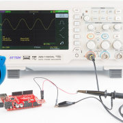
A logic-analyzer capture at a 24 MHz sample rate showed the resulting signals synchronized well enough for the proof of concept. The author was appropriately cautious about whether synchronization would remain reliable at substantially higher speeds.
But the architectural implication was much bigger than the eight-bit test.
If multiple FlexIO peripherals could reliably cooperate, a future library might no longer require every data bit to belong to one convenient contiguous group. The discussion estimated that arbitrary combinations could potentially reach as many as 26 FlexIO pins on Teensy 4.0, 32 on MicroMod, and 38 on Teensy 4.1, though using FlexIO3 means falling back to interrupt-driven servicing rather than DMA.
That's getting pretty close to a little programmable I/O fabric hiding inside a microcontroller.
The 50 MHz ADC Question
Output is only half the problem.
PJRC forum member jonr pushed the input side considerably harder, asking whether FlexIO could capture a 12-bit parallel ADC at about 50 MHz with low jitter.
That sounded plausible at first, but I had some concerns about the difference between FlexIO's internal clock rate and the maximum rate of an external signal it could reliably receive. Incoming pins have to pass through synchronization logic before the FlexIO hardware can use them, and the RT1062 reference manual specifically calls out synchronization delays in SPI slave mode. My feeling was that 50 MHz might be beyond what FlexIO could reliably handle, though there was still some room for experimentation.
Incoming pins have to pass through synchronization logic before the FlexIO machinery can use them. I pointed specifically to the RT1062 reference manual's discussion of pin synchronization and noted that SPI slave operation is also limited by synchronization delays. His conclusion was deliberately cautious: a 50 MHz externally clocked parallel interface might be beyond what FlexIO can reliably do.
That's exactly the kind of caveat that matters when working this close to the silicon.
A 120 MHz peripheral clock does not imply:
maximum external data rate = 120 MHzThere are synchronizers, setup and hold requirements, internal paths, DMA response times, and eventually memory bandwidth to consider.
Overclocking FlexIO doesn't make those considerations disappear either. Forum experiments reported operation with FlexIO clocks above the documented 120 MHz value, including 240 MHz and even 480 MHz in some circumstances, but also reported instability and missed behavior as clocks were pushed outside their intended relationships.
For a library intended for general use, documented operation and “it worked on my logic analyzer” need to remain two different categories.
Sometimes the Answer Isn't FlexIO
This is where the second forum discussion becomes useful.
In a separate PJRC forum discussion, member JoCaGoVi (Jose) was wrestling with a different high-speed interface problem: communicating with a custom SPI slave at up to 50 MHz through level translators required by the target's 1.2 V and 1.8 V signaling.
At low speeds, propagation delay through the level shifter isn't particularly exciting.
At 50 MHz, one clock period is only 20 ns.
Now the round-trip timing of SCLK, the target's output delay, the translator delay on MISO, and the Teensy's sampling point all start eating into the same timing budget.
Jose noticed the RT1062's DQS capability and wondered whether a delayed clock or data strobe could be used to sample MISO after those propagation delays.
It's a good idea.
It just isn't a FlexIO feature.
FlexSPI and DQS
Before getting into code, I wanted to clear up one potentially confusing part of the RT1062 architecture. The DQS functionality Jose had found belongs to FlexSPI, not FlexIO or LPSPI.
The DQS functionality Jose had found belongs to FlexSPI.
That's the high-speed memory-oriented peripheral, not LPSPI and not FlexIO.
FlexSPI can operate with a one-bit data interface, so in principle Jose's idea wasn't ruled out. But using FlexSPI for a custom device isn't simply a matter of replacing SPI.transfer() with FlexSPI.transfer(). Its operation is programmed through instruction sequences in LUT memory.
There was also a physical problem.
The relevant DQS pins aren't conveniently exposed as ordinary Teensy 4.1 pins. I noted that one possible FlexSPI2 DQS signal, GPIO_SD_B0_05, is routed to the built-in SD-card socket, while another possible DQS location isn't routed on the standard Teensy 4.1 at all. A custom board could expose the required signals, but now we're well outside plug-and-play Arduino territory.
This gets at an important point when working with Teensy 4.x: the Arduino libraries intentionally support only a subset of everything the RT1062 hardware can do. Once a project needs something outside that subset, the reference manual becomes part of the development environment.
The Arduino libraries support a subset of what the RT1062 hardware can do.
Once your application needs something outside that subset, the reference manual becomes part of the development environment.
Flexibility Isn't the Same as Magic
FlexIO is tempting because it looks a little like programmable logic.
And in a limited sense, it is.
We get shifters, timers, state and control logic, flexible pin routing, interrupts, and in some cases DMA. With some creativity, those pieces can implement interfaces the designers of the board never specifically anticipated.
But it isn't an FPGA.
The pins still have fixed routing options. Shifter resources are finite. FlexIO instances don't all have identical DMA capability. Incoming signals pass through synchronization paths. DMA shares memory bandwidth with the rest of the system. External memory has its own limits.
There's even a subtle example buried at the end of the parallel-interface discussion. The proof-of-concept enabled FlexIO's FASTACC mode while running FlexIO at 120 MHz. Later in the thread, PJRC forum member AndyA spotted a subtle issue in the proof-of-concept code: NXP specifies FlexIO's fast register-access mode only when the FlexIO functional clock is at least twice the bus-clock frequency. With the bus at 150 MHz, that condition wasn't satisfied. They had observed extremely rare lockups—roughly once per gigabytes of output—and reported that disabling fast access appeared to eliminate them.
That's the sort of bug that reminds you what level you're working at.
The code compiles. The interface runs. The logic analyzer looks right. And two gigabytes later, one sentence in the reference manual suddenly matters a lot.
The Bigger Lesson
I don't think the most interesting takeaway from these experiments is “FlexIO makes fast parallel displays.”
It certainly can help do that.
The bigger idea is that the peripheral names printed on a microcontroller's feature list aren't necessarily the boundaries of what the hardware can do.
Teensy 4.1 already exposes a remarkable collection of fixed-function peripherals: SPI, I2C, UARTs, CAN, I2S, SDIO, USB, Ethernet, DMA, and more. FlexIO sits alongside them as something different: a set of hardware building blocks for the interfaces that don't fit cleanly into one of those categories.
Most projects should use those conventional peripherals and their libraries. They're easier to understand, easier to maintain, and much harder to get subtly wrong.
But occasionally the interface itself is the interesting engineering problem.
Maybe you need 12 parallel inputs synchronized to an external clock. Maybe your display wants a wide 8080 bus. Maybe an ADC shifts several samples simultaneously. Maybe you need a hardware-generated clock while the CPU handles something else. Maybe your signals don't even fit on one FlexIO peripheral.
At that point, don't start by asking which Arduino library has the function you need.
Start by asking what the signals need to do. Then:
- Look at the shifters.
- Look at the timers.
- Look at the pin mux.
- Look at the synchronization path.
- Look at DMA and memory bandwidth.
- And, yes, open the reference manual. Because sometimes the peripheral you need isn't one NXP put a name on. Sometimes you have to build it yourself :)
Further Reading
The best starting point for the underlying silicon is NXP's i.MX RT1060 Processor Reference Manual. For the Teensy side, PJRC's Teensy 4.1 technical information covers the board's FlexIO capability, pin information, DMA resources, and other peripheral details. PJRC's introduction to FlexIO_t4 is also a useful overview of the library's shifters, timers, resource management, FlexSerial, and FlexIOSPI.
Footnote
This article is based on the PJRC forum thread Ideas on a T4 parallel library using FlexIO and FlexIOSPI with DQS and the discussion that followed between forum members.